Boomerang

a boomerang and kinetic energy technology, applied in the field of boomerangs, can solve the problems of reducing the amusement effect of players, so as to increase the kinetic energy of the boomerang, increase the inertia weight of the boomerang, and simple construction.

Active Publication Date: 2013-12-17
TOSY ROBOTICS
View PDF32 Cites 6 Cited by
  • Summary
  • Abstract
  • Description
  • Claims
  • Application Information

AI Technical Summary

Benefits of technology

[0007]Accordingly, it is a general object of the present invention to provide a boomerang having blades that can automatically change their elevation angle and their curve radius upon the change of rotary speed of the blades thanks to a special construction of the blade shape as well as type of material of which the blades are made.
[0016]Model 1: when v (blade speed) increases, then α decreases, blades curve radius r increases, Fl and Fd decrease; and on the contrary when v decreases, then α increases, r decreases, Fl and Fd increase. This creates an unexpectedly desirable effect in that the lift force is in inverse proportion to the blades speed that keeps both the boomerang not to elevate so high and its flying time prolonged.
[0020]The remarkable advantage of the boomerang of the present invention is of its very simpleness in construction but easiness in adjusting the relevant parameters (the hardness of the material of which the blades are made, the width of each end of the blades, the initial elevation angle α0, curve radius, etc.) in order to gain the desirable effect of automatic adjustment of the elevation angle α, resulting in automatic adjustment of lift force and drag force upon blades speed. Such an effect so far just have been achieved by only relatively complicated systems as mentioned in the Background Art part.
[0021]In order to increase the inertia weight of the boomerang of the present invention, thereby increasing the kinetic energy of the boomerang of the invention, the boomerang may be further designed in such way that its weight is distributed far from its center, for example the electric source and the light lamps such as light emitting diodes (LEDs) may be located on / inside the ring of the boomerang. Such a creative distribution of weight additionally contributes to keep the boomerang of the invention have its flying time longer than usual.

Problems solved by technology

Concurrent with such a high lift force, an air-drag force effecting on the blades of the rotor is high too, that results in decreasing the rotary speed of the rotor.
That means the flying rotors having blades with fixed elevation angle will have their flying time relatively short that decreases the amusement effect to players.
Moreover, since the flying time of such a flying rotor is too short, so the rotor has not time enough for flying back to its launching position, so-called “boomerang effect”.
That further decreases the amusement effect to players.
However, these toys seem relatively complicated; they need an elevation angle control means for changing the angle according to the rotary speed of the blades.

Method used


Image

  • Boomerang
  • Boomerang
  • Boomerang

Examples


Embodiment Construction

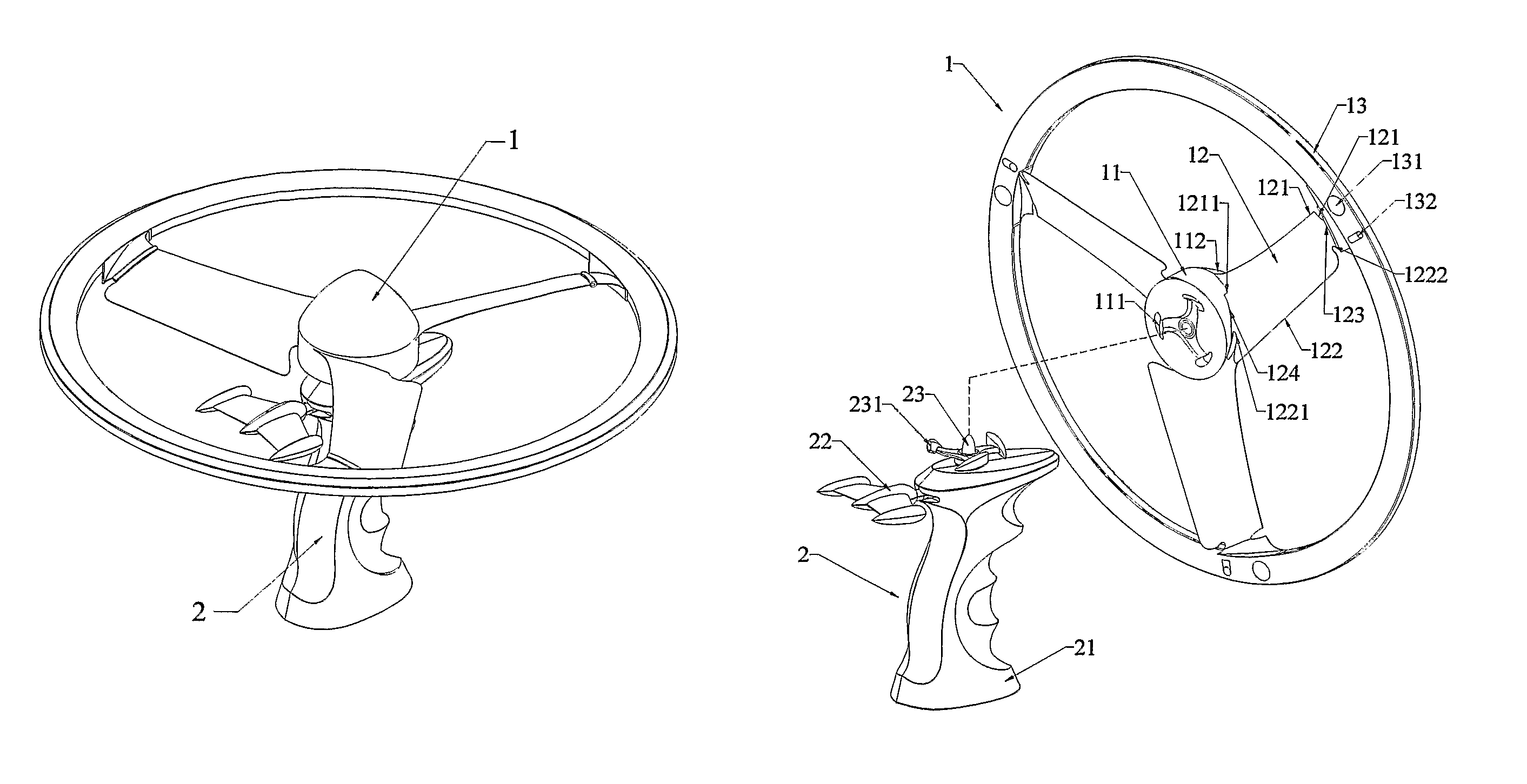
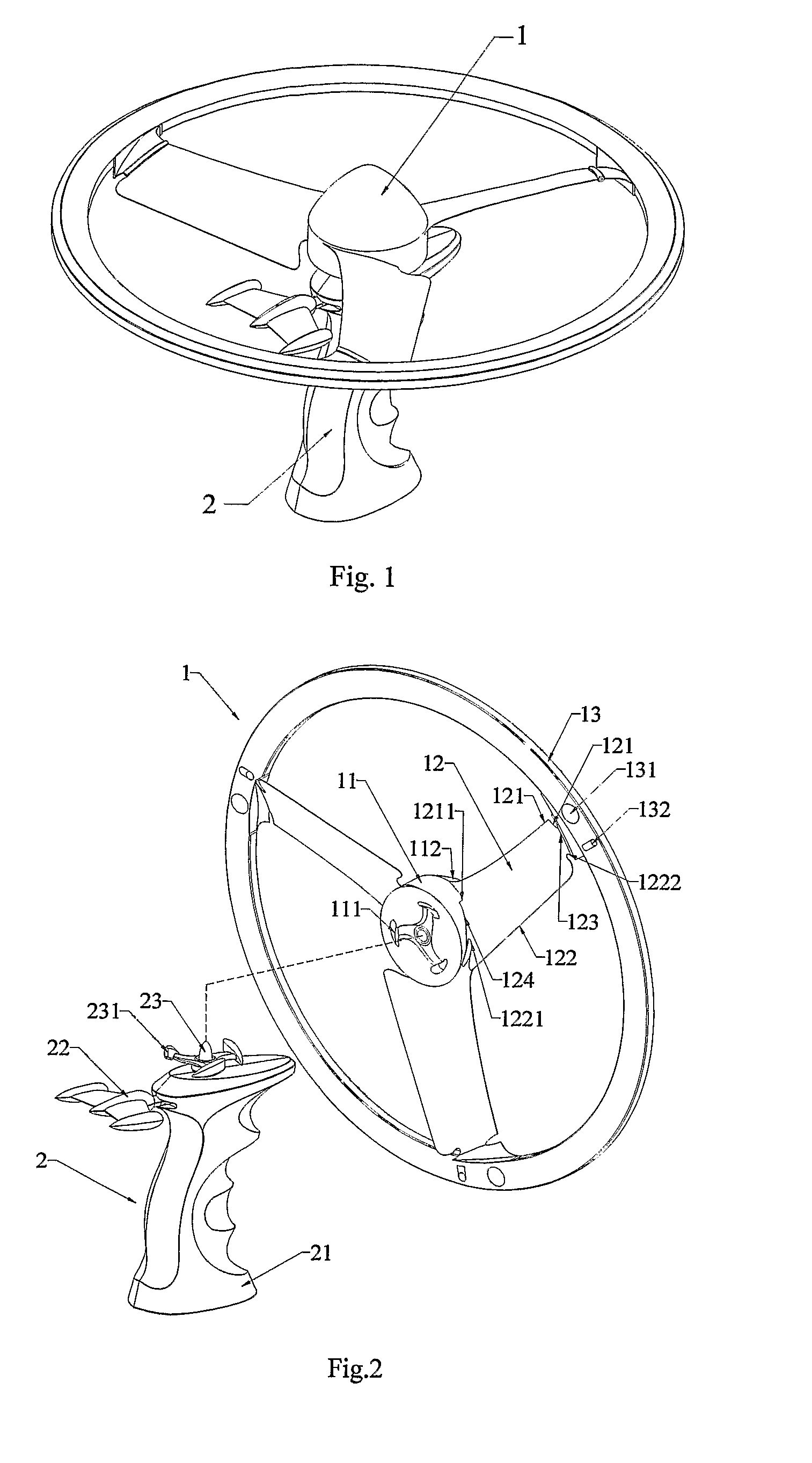
[0033]FIG. 1 shows a boomerang 1 according to a preferred embodiment of the present invention mounted on a hand-held launcher 2. The hand-held launcher 2 has an upper part that may be detachably fitted to a center part of the boomerang 1. The hand-held launcher 2 is capable of transferring a rotary movement to the boomerang 1. Since there is no improvement on the hand-held launcher 2, description of the handheld launcher 2 can be ignored.

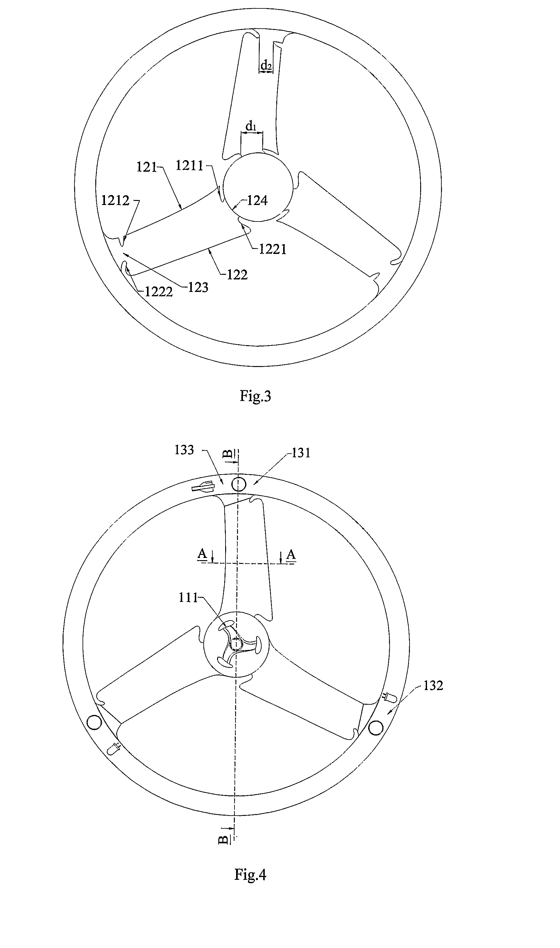
[0034]The boomerang 1 comprises at least two blades 12 radially extending from the center part 11. In a preferred embodiment, the boomerang 2 comprises three blades. The blades 12 have an initial elevation angle α0. The initial elevation angle α0 preferably has a value of from about 10° to about 45°. The center part 11 is a closed part having a round perimeter, its bottom side provides a means for attaching to the upper part of the hand-held launcher 2 (see FIG. 2). The upper part of the center part 11 preferably has an aerodynamic shape, such as a ...


PUM


Abstract

The invention relates to a boomerang that can automatically change both elevation angle α of blades and curve radius r of blades upon the change of rotary speed of blades (12), wherein blades (12) are made of elastically plastic film preferably selected from a group of polyvinyl chloride, polypropylene, polyethylene terephthalate, polystyrene and high impact polystyrene, the material has a specific weight of from about 0.9 g / cm3 to about 1.60 g / cm3 and as thickness from about 0.1 mm to about 1 mm; the ratio between the depth of the rear groove and blade width is from about 1 / 7 to about 6 / 7; the ratio between depth of the front groove and blade width is from about 0 to about 3 / 7; the elevation angle α0 is from about 10° to about 45°; the initial curve radius r0 of the blades is longer or equal to 1 / 5 of the radius R of said ring (13); the ratio between the total area of said blades and the area of a circle defined by said ring (13) is from about % to about 38%.

Description

[0001]This patent application is a nation stage application under 35 U.S.C. §371 of international application PCT / VN2008 / 000004, filed on Oct. 9, 2008, which claims priority to Vietnamese patent application number 1-2007-02103, filed on Oct. 12, 2007, the entire contents of which are hereby incorporated by reference in their entireties.TECHNICAL FIELD[0002]The present invention relates to a boomerang having a round ring with blades inside that can fly by means of a launching force and then can fly back to its launching position. More specifically, this invention relates to a boomerang that can automatically change both the elevation angle of the blades and the curve radius of the blades upon the change of rotary speed of the blades thanks to a special construction shape of the blades as well as the material of which the blades are made.BACKGROUND ART[0003]There have been many flying toys having rotor which can fly by means of receiving a rotary movement that makes the rotor spin aro...

Claims


Application Information

Patent Timeline
Patent Type & Authority Patents(United States)
IPC IPC(8): A63F3/00
CPCA63H27/12A63H33/18
Inventor HOANG, HO VINH
Owner TOSY ROBOTICS
Why Eureka
Try Eureka