Stator for electric rotating machine

a technology of rotating machines and stator frames, which is applied in the direction of dynamo-electric machines, magnetic circuit shapes/forms/construction, supports/enclosements/casings, etc., can solve the problems of increasing the number of components and requiring more assembly time, so as to reduce the diameter of the stator frame, reduce the number of components needed, and distribute the weight

Inactive Publication Date: 2011-04-12
MITSUBISHI ELECTRIC CORP
View PDF6 Cites 8 Cited by
  • Summary
  • Abstract
  • Description
  • Claims
  • Application Information

AI Technical Summary

Benefits of technology

[0006]The present invention has been implemented in order to solve the foregoing problems in the conventional technology; the objective thereof is to obtain a stator, for an electric rotating machine, that makes it possible to reduce the diameter of the stator frame and to decrease the number of components needed to distribute the weight.
[0008]In the present invention, the elastic supporting members are each fixed to the inner circumferential surfaces of the inner frame members that are adjacent to one another, and that are each fixed to the outer circumferential surfaces of the holding rings at the middle in the axis direction, or that are each fixed to the outer circumferential surfaces of the holding rings that are adjacent to each other, and that are each fixed to the inner circumferential surfaces of the inner frame members at the middle in the axis direction; therefore, not only can the size of an electric rotating machine be reduced, but also the foregoing configuration enables the weight to be readily distributed and the number of components to be decreased.

Problems solved by technology

In such a conventional stator for an electric rotating machine as described above, the bending prevention means can prevent eternal deformation due to the excessive torque; however, because the screen plates are provided at positions facing the respective outer circumferential surfaces of the stator supporting plates, there has been a problem that the outer diameter of a frame becomes large.
Moreover, because the stator iron core is elastically supported by the spring rods, a great number of spring rods are required in the circumferential direction, in order to distribute the weight such as the gravity of the stator iron core and the rotation torque in the circumferential direction; therefore, there has been a problem that increase in the number of components requires more time for assembly work.

Method used


Image

  • Stator for electric rotating machine
  • Stator for electric rotating machine
  • Stator for electric rotating machine

Examples


embodiment 1

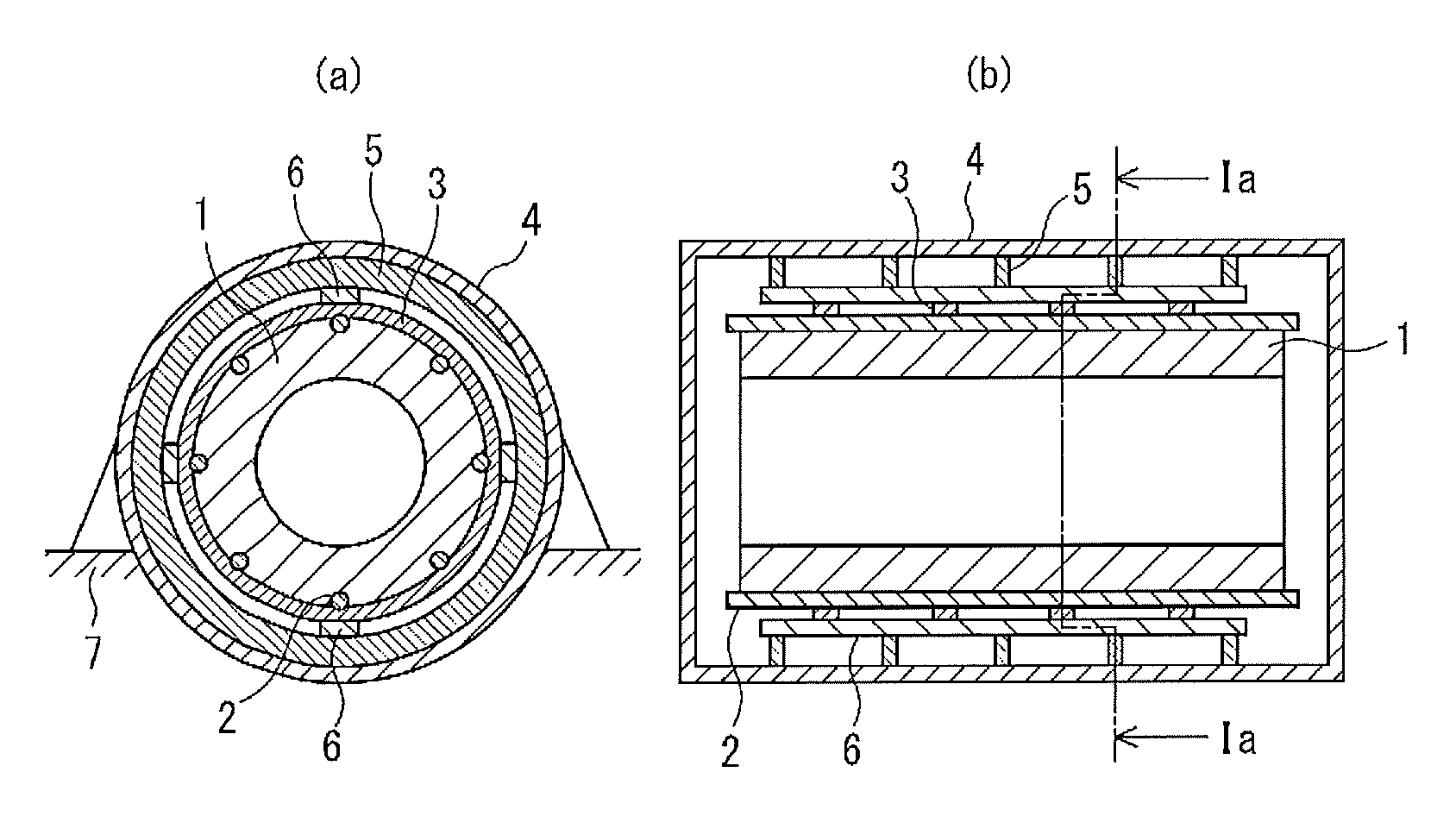
[0019]A stator for an electric rotating machine according to Embodiment 1 of the present invention will be explained below with reference to FIG. 1. In FIG. 1, a stator for an electric rotating machine is provided with a cylindrical stator iron core 1; a plurality of (eight, in this example) iron core fastening members 2 that are provided spaced a predetermine distance apart from one another in the circumferential direction on the outer circumferential surface of the stator iron core 1 and screw the stator iron core 1 in the axis direction (a direction in parallel with the axis of the stator iron core 1); a plurality of (four, in this example) axis-direction-flattened holding rings 3 that are provided spaced a predetermine distance apart from one another in the axis direction on the outer circumferential surface of the stator iron core 1 and hold the stator iron core 1 as if to press the stator iron core 1 toward its center portion by the intermediary of the iron core fastening memb...

embodiment 2

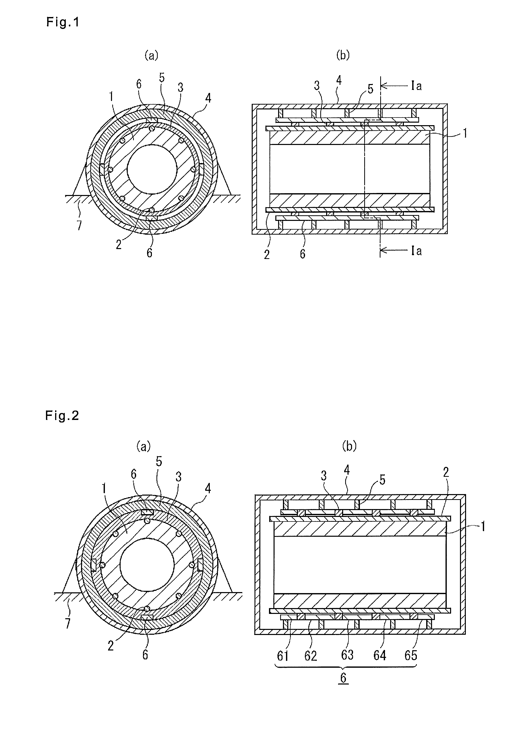
[0025]Next, a stator for an electric rotating machine according to Embodiment 2 of the present invention will be explained with reference to FIG. 2. In addition, the same reference characters in figures denote the same or equivalent constituent elements. In FIG. 2, a holding ring 3 is the same or slightly larger than the holding ring 3 in Embodiment 1 in the radial-direction cross-sectional size; the cross section thereof is almost square. An elastic supporting member 6 is divided into elastic supporting members 61 to 65 arranged in the axis direction; each of the divided elastic supporting members 62 to 64 is disposed at the outer surface side that is situated between the side faces, of the adjacent holding rings 3, which face each other in the axis direction, and is joined, through welding or by means of a bolt, with the side faces, of the adjacent holding rings 3, which face each other. Each of the elastic supporting members 61 and 65 at both ends in the axis direction is constru...

embodiment 3

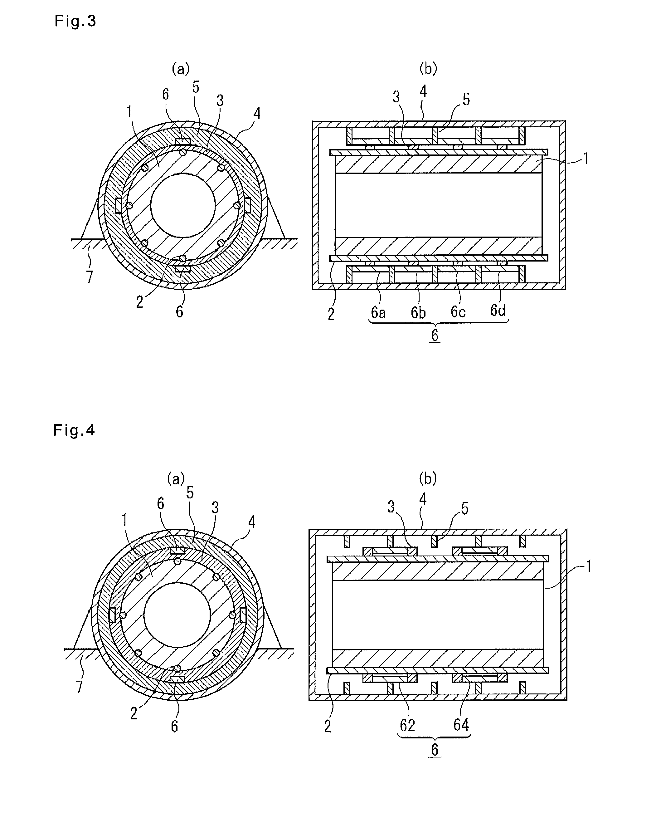
[0027]Next, a stator for an electric rotating machine according to Embodiment 3 of the present invention will be explained with reference to FIG. 3. In FIG. 3, an elastic supporting member 6 is divided into elastic supporting members 6a to 6d arranged in the axis direction; each of the divided elastic supporting members 6a to 6d is disposed at the inner surface side that is situated between the side faces, of the adjacent inner frame members 5, which face each other in the axis direction, and is joined, through welding or by means of a bolt, with the side faces, of the adjacent inner frame members 5, which face each other. As is the case with Embodiment 1, each of the elastic supporting members 6a to 6d is joined with the outer circumferential surface of the holding ring 3.

[0028]In Embodiment 3 configured as described above, because the elastic supporting members 6a to 6d are separately arranged in such a way as to be inserted between the adjacent inner frame members 5 that face eac...


PUM


Abstract

A stator for an electric rotating machine has iron core fastening members on the outer circumferential surface of a stator iron core, spaced apart from one another in a circumferential direction and fastened to the iron core in an axial direction. Holding rings on the outer circumferential surface of the iron core, spaced apart from one another in the axial direction, press the iron core toward a center portion thereof via the iron core fastening members. Ring-shaped inner frame members protrude from the inner surface of a frame that encloses the iron core, and are spaced apart from one another in the axial direction. Elastic supporting members are fixed to the inner circumferential surfaces of the inner frame members that are adjacent to one another, and are fixed to the outer circumferential surfaces of the holding rings at the middle in the axial direction, or vice versa.

Description

BACKGROUND OF THE INVENTION[0001]1. Field of the Invention[0002]The present invention relates to a stator for an electric rotating machine, and more particularly to improvement of a structure for elastically supporting a stator iron core in a frame.[0003]2. Description of the Related Art[0004]Among electric rotating machines in which a stator iron core is elastically supported, by the intermediary of iron core supporting plates, by a plurality of spring rods arranged in the axis direction of the stator iron core on a circumference in the vicinity of the outer circumferential surface of the stator iron core, there exists an electric rotating machine having a conventional stator, for the electric rotating machine, in which screen plates are provided at positions facing the outer circumferential surfaces of the respective iron core supporting plates, and there is provided a bending prevention means that forms, between the iron core supporting plate and the screen plate, a predetermined...

Claims


Application Information

Patent Timeline
Patent Type & Authority Patents(United States)
IPC IPC(8): H02K1/06
CPCH02K5/24H02K1/185
Inventor KIKUICHI, YOSHIHIDE
Owner MITSUBISHI ELECTRIC CORP
Why Eureka
Try Eureka