Method for autonomous operation of electricity-generating device

an electricity-generating device and autonomous technology, applied in the direction of electric generator control, machines/engines, mechanical equipment, etc., can solve the problems of difficulty in realizing system interconnection, disadvantageous aspects of installation places, and cos

Active Publication Date: 2017-07-27
MEIDENSHA ELECTRIC MFG CO LTD
View PDF8 Cites 0 Cited by
  • Summary
  • Abstract
  • Description
  • Claims
  • Application Information

AI Technical Summary

Benefits of technology

[0015]As described above, according to the present invention, even when parallel-off of the electricity-generating device from the electric power system is performed, the autonomous operation of the electricity-generating device is realized with the energy balance corresponding to the load within a speed range of the rated speed or more in the efficiency-characteristics curve. Accordingly, even when it is difficult for the electricity-generating device to perform system interconnection, the autonomous operation control can be performed without specially preparing a device for an isolated operation such as a dummy resistor device or a high-speed guide vane control unit by an electric servo motor.

Problems solved by technology

In the case where the small and medium-scaled electricity-generating device is operated by being interconnected to the electric power system, there may be a case where it is difficult to realize system interconnection when some kind of abnormality occurs in the electric power system as an interconnect destination.
However, it is necessary to add a peculiar operation function in that case, which is disadvantageous in aspects of an installation place and costs.

Method used


Image

  • Method for autonomous operation of electricity-generating device
  • Method for autonomous operation of electricity-generating device
  • Method for autonomous operation of electricity-generating device

Examples


Embodiment Construction

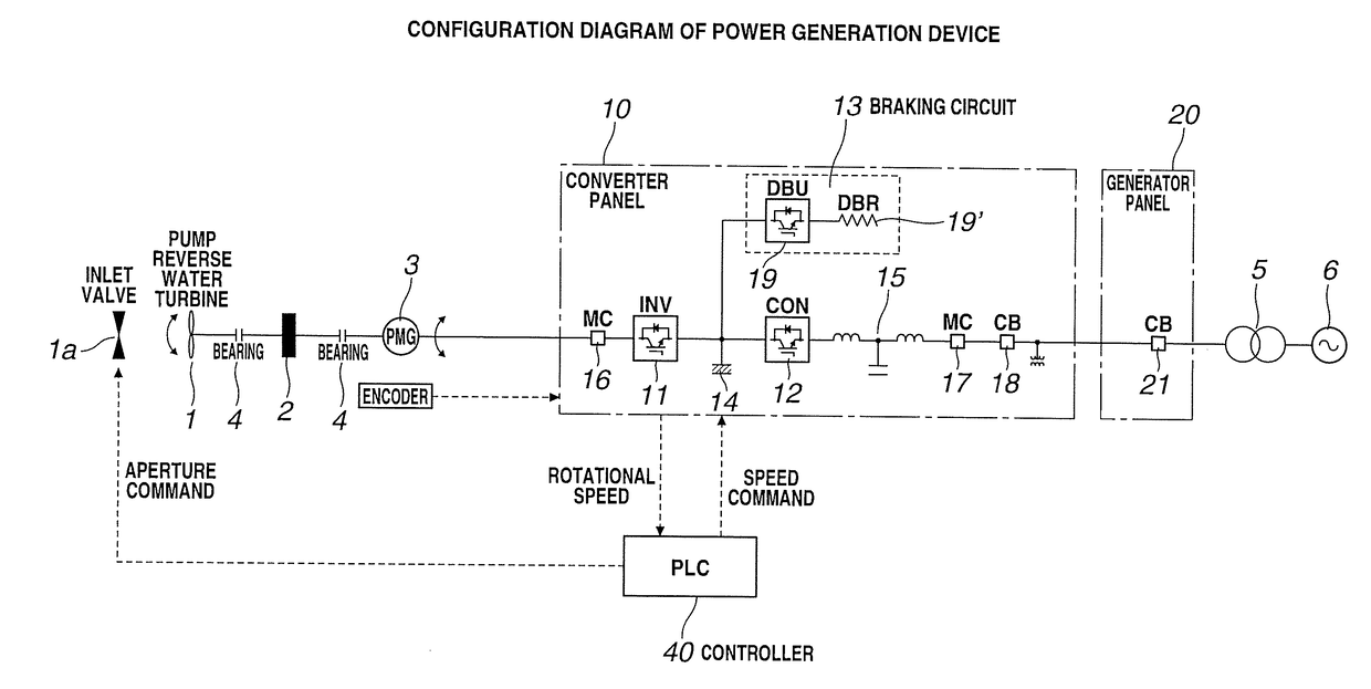
[0024]FIG. 1 is a schematic diagram showing an electricity-generating device according to the present Embodiment 1. FIG. 1 differs from FIG. 7 which shows a conventional electricity-generating device in a point that a dummy load device is omitted. Other points are the same as FIG. 7, therefore, explanation will be omitted.

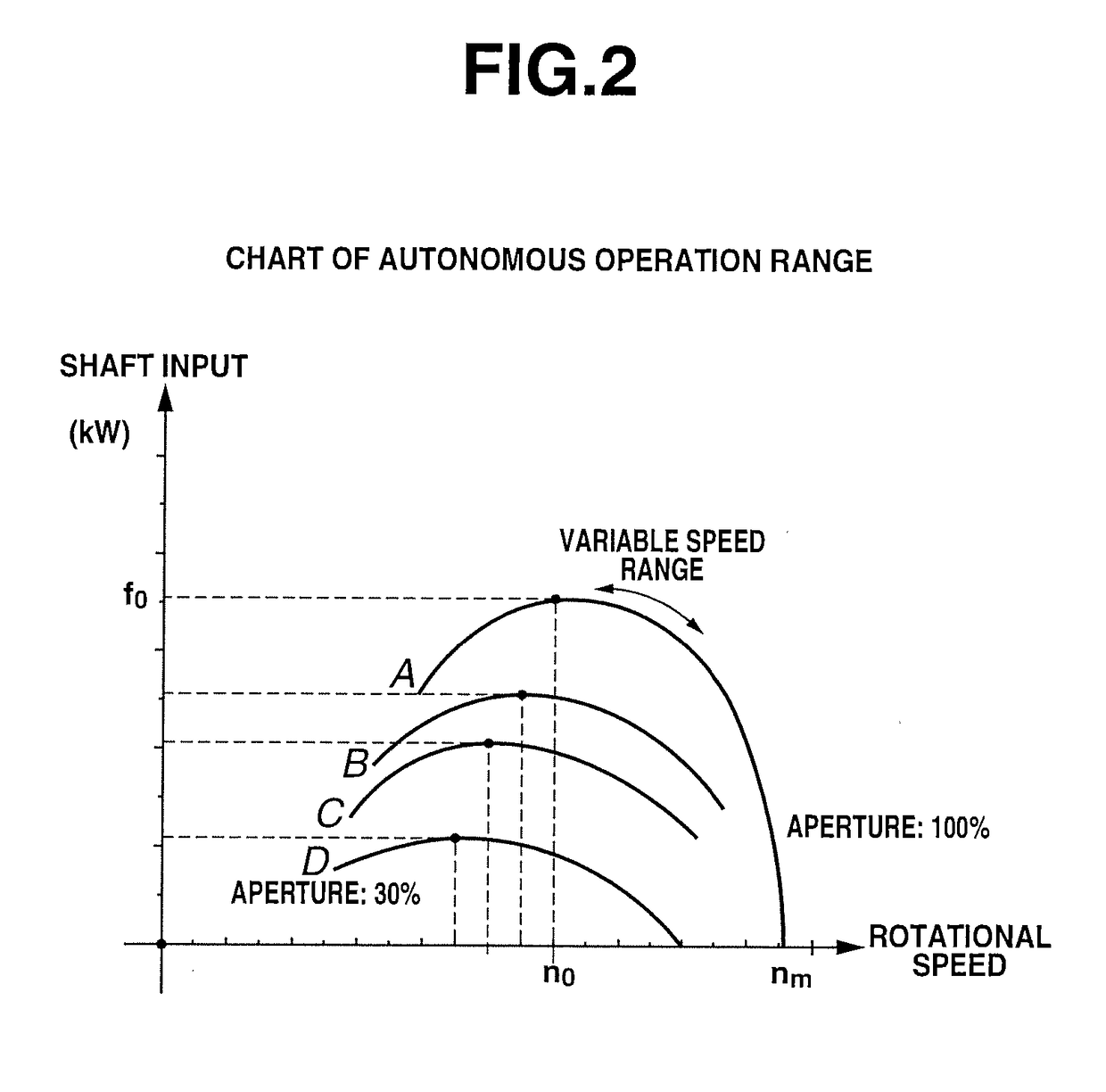
[0025]FIG. 2 shows efficiency-characteristics curves (hereinafter referred to as Cp characteristics curves) of a water turbine. When a rated capacity of a permanent magnet power generator is f0 and a rated speed thereof is n0, the shaft input is increased from a line D to a line A in accordance with an aperture of an inlet value 1a of a water turbine 1, and the generator is operated in the vicinity of the rated speed n0 at the time of system interconnection.

[0026]In the present invention, the autonomous operation is performed with respect to the load capacity which is lower than a rated capacity of the permanent magnet power generator in the case where the system i...


PUM


Abstract

When it is not possible for a power generation device to operate coupled to an electric power system, an autonomous operation of connection and disconnection of a load of the power generation device is performed along an efficiency-characteristics curve within a speed range from a rated speed to a maximum speed in the efficiency-characteristics curve of an energy source. During the autonomous operation, an aperture command is outputted to an inlet valve of a water turbine and a first converter is operated in a converter mode when an operation preparation command is outputted by a control unit, a second converter is operated in an inverter mode when a voltage is established by of a DC linkage unit, and the load is connected when the operation preparation is completed.

Description

TECHNICAL FIELD[0001]The present invention relates to a method for an autonomous operation of an electricity-generating device, and particularly relates to a method for an autonomous operation by an electricity-generating device using a permanent magnet power generator.BACKGROUND ART[0002]An electricity-generating device using a permanent magnet power generator as a small and medium-sized power generator and using a wind turbine or a water turbine as an energy source is attracting attention. FIG. 7 shows a single connection diagram of a water-turbine electricity-generating device using the permanent magnet power generator, and the water-turbine electricity-generating device is interconnected to an electric power system 6 through an interconnection transformer 5. In FIG. 7, Numeral 1 denotes a water turbine, numeral 2 denotes a flywheel and numeral 3 denotes a permanent magnet power generator, which are coupled through bearings 4.[0003]Numeral 10 denotes a converter panel, and the co...

Claims


Application Information

Patent Timeline
Patent Type & Authority Applications(United States)
IPC IPC(8): H02P9/04F03B13/08F03B15/06H02K7/18
CPCH02P9/04F03B15/06F03B13/08H02K7/1823F03B15/005F03B15/04F05B2220/7068H02J3/388Y02E10/20
Inventor MASUKO, TOSHITAKE
Owner MEIDENSHA ELECTRIC MFG CO LTD
Why Eureka
Try Eureka