Mixing impeller, method of manufacturing a first subassembly of the mixing impeller and method of assembling the mixing impeller

Active Publication Date: 2017-08-03
SARTORIUS STEDIM BIOTECH GMBH
View PDF7 Cites 2 Cited by
  • Summary
  • Abstract
  • Description
  • Claims
  • Application Information

AI Technical Summary

Benefits of technology

[0017]The second subassembly may be made of plastic so that the second subassembly can be manufactured cheaply.
[0018]If the mixing vessel is reusable, the first subassembly may be considered as a permanent element in a mixing vessel and the second subassembly may be chosen and changed, if required, depending on the mixi

Problems solved by technology

Some applications require that the mixing equipment is fully closed with no possibility of leakage between the mixing vessel and the environment—for example, the fluids to be mixed are either hazardous (e.g. toxic) or if they are sensitive to contamination from the outside environment (e.g. highly purified pharmaceutical mater

Method used


Image

  • Mixing impeller, method of manufacturing a first subassembly of the mixing impeller and method of assembling the mixing impeller
  • Mixing impeller, method of manufacturing a first subassembly of the mixing impeller and method of assembling the mixing impeller
  • Mixing impeller, method of manufacturing a first subassembly of the mixing impeller and method of assembling the mixing impeller

Examples


Embodiment Construction

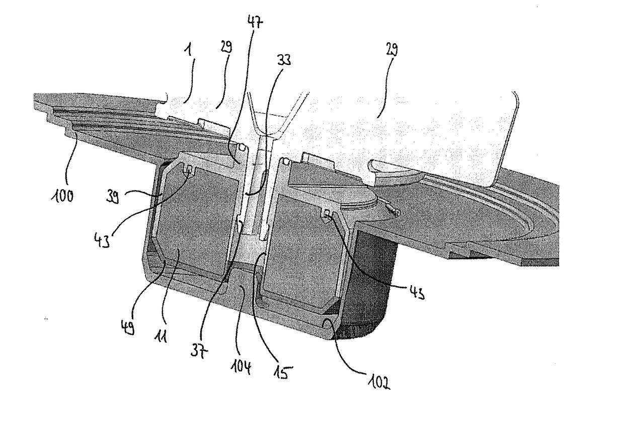
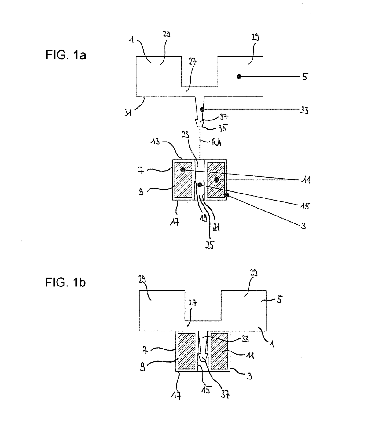
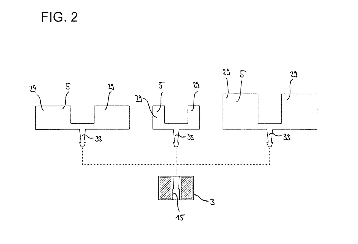
[0062]FIG. 1 shows a cross sectional view of a mixing impeller 1 for mixing components in a mixing vessel. The mixing impeller 1 comprises a first subassembly 3 and a second subassembly 5 that are separately formed, but that are connectable by means of an engagement mechanism. FIG. 1a) shows a state before the first subassembly 3 and the second subassembly 5 are connected. FIG. 1b), however, shows a mounted state of the mixing impeller 1, in which the first and second subassemblies 3, 5 are connected / engaged.

[0063]The first subassembly 3 comprises a housing 7 that preferably has a circular shape and / or is made of plastic. At least one accommodation space 9 is provided inside of said housing 7 for accommodating a magnet 11. If more than one accommodation space 9 is formed in the first subassembly 3, preferably each of the accommodation spaces 9 is filled with a magnet 11. In the case of FIG. 1, one accommodation space 9 is formed in the housing 7 and has a ring-shape. A ring-shaped m...


PUM

PropertyMeasurementUnit
Sizeaaaaaaaaaa

Abstract

A mixing impeller has first and second subassemblies. A magnet is accommodated in the first subassembly and is adapted to be magnetically coupled to a drive device to be driven. The second subassembly has at least one impeller blade for mixing components when rotating the mixing impeller. The first and second subassemblies are formed as separate entities which are selectively engageable. A method of manufacturing the first subassembly and a method of assembling the mixing impeller also are provided.

Description

BACKGROUND[0001]1. Field of the Invention[0002]The invention refers to a mixing impeller including two engageable subassemblies, a method of manufacturing one of the subassembly and a method of assembling the two subassemblies.[0003]2. Related Art[0004]In the conventional engineering practice, a mixing device comprises a mixing vessel containing fluids to be mixed and a motor driving a shaft to which one or more mixing impellers are fixed. The mixing impeller may be mounted to the shaft by a hub which is bolted or welded in place so that it does not come loose during operation. The mixing impeller is typically specified along with the mixing vessel according to design guidelines (for example, Handbook of Industrial Mixing, Paul et al.) so as to achieve the desired performance. Unless there is a process change or a need for refurbishment the mixing impeller remains fixed to the shaft.[0005]Some applications require that the mixing equipment is fully closed with no possibility of leak...

Claims


Application Information

Patent Timeline
IPC IPC(8): B01F7/00B29C45/14B01F13/08
CPCB01F7/00341B01F7/0025B29K2995/0008B29C45/1418B01F13/0827B29C45/14819B29D99/0082B29C45/14778B29C45/1671B01F33/453B01F35/513B01F35/561B01F27/113B01F27/112
Inventor BOETTCHER, LARSCUTTING, JONATHAN E.WEST, SHARON D.OSCHWALD, MARTINBATES, MIKE
Owner SARTORIUS STEDIM BIOTECH GMBH
Why Eureka
Try Eureka