Liquid ejecting unit, liquid ejecting head, support body for liquid ejecting head

a technology of liquid ejecting head and support body, which is applied in the direction of printing, inking apparatus, etc., can solve the problems of limited size of the whole device, reduce the size of the first support body, increase the mechanical strength of the support body, and reduce the size of the support body for the liquid ejecting head.

Active Publication Date: 2017-08-03
SEIKO EPSON CORP
View PDF4 Cites 7 Cited by
  • Summary
  • Abstract
  • Description
  • Claims
  • Application Information

AI Technical Summary

Benefits of technology

[0015]According to another preferred aspect (Aspect 9) of the invention, there is provided a liquid ejecting head, including: a first liquid ejecting unit and a second liquid ejecting unit each in which a plurality of nozzles for ejecting liquid are formed on the ejecting face; and a first support body that supports the first liquid ejecting unit and the second liquid ejecting unit, in which a first opening portion that exposes the ejecting face of the first liquid ejecting unit and a second opening portion that exposes the ejecting face of the second liquid ejecting unit are formed on the first support body along a first direction, and in which a beam-shaped portion between the first opening portion and the second opening portion includes a first support portion to which the first liquid ejecting unit is fixed and a second support portion to which the second liquid ejecting unit is fixed. According to the Aspect 9, the first support portion and the second support portion are formed on the beam-shaped portion between the first opening portion that exposes the ejecting face of the first liquid ejecting unit and the second opening portion that exposes the ejecting face of the second liquid ejecting unit, and thus there is an advantage in that the size of the first support body can be reduced.
[0016]In a preferred example (Aspect 10) of the Aspect 9, the beam-shaped portion may include an intermediate portion that couples the first support portion and second support portion. According to the Aspect 10, the beam-shaped portion is formed in a shape in which the first support portion, the second support portion, and the intermediate portion are coupled to each other, and thus it is possible to increase the mechanical strength of the support body compared to a configuration in which the first support portion and the second support portion are separated from each other.
[0017]According to still another preferred aspect (Aspect 11) of the invention, there is provided a support body for a liquid ejecting head that supports a first liquid ejecting unit and a second liquid ejecting unit each in which a plurality of nozzles for ejecting liquid are formed on the ejecting face, in which a first opening portion that exposes the ejecting face of the first liquid ejecting unit and a second opening portion that exposes the ejecting face of the second liquid ejecting unit are formed along a first direction, and in which a beam-shaped portion between the first opening portion and the second opening portion includes a first support portion to which the first liquid ejecting unit is fixed, and a second support portion to which the second liquid ejecting unit is fixed. According to the Aspect 11, the first support portion and the second support portion are formed on the beam-shaped portion between the first opening portion that exposes the ejecting face of the first liquid ejecting unit and the second opening portion that exposes the ejecting face of the second liquid ejecting unit, and thus there is an advantage in that the size of the support body for a liquid ejecting head can be reduced.
[0018]In a preferred example (Aspect 12) of the Aspect 11, the beam-shaped portion may include an intermediate portion that couples the first support portion and second support portion. According to the Aspect 12, the beam-shaped portion is formed in a shape in which the first support portion, the second support portion, and the intermediate portion are coupled to each other, and thus it is possible to increase the mechanical strength of the support body compared to a configuration in which the first support portion and the second support portion are separated from each other.

Problems solved by technology

However, in the technique disclosed in JP-A-2010-179499, since the plurality of liquid ejecting heads are disposed on the base plate in parallel, there is a problem that a reduction in the size of the whole device is limited.

Method used


Image

  • Liquid ejecting unit, liquid ejecting head, support body for liquid ejecting head
  • Liquid ejecting unit, liquid ejecting head, support body for liquid ejecting head
  • Liquid ejecting unit, liquid ejecting head, support body for liquid ejecting head

Examples


first embodiment

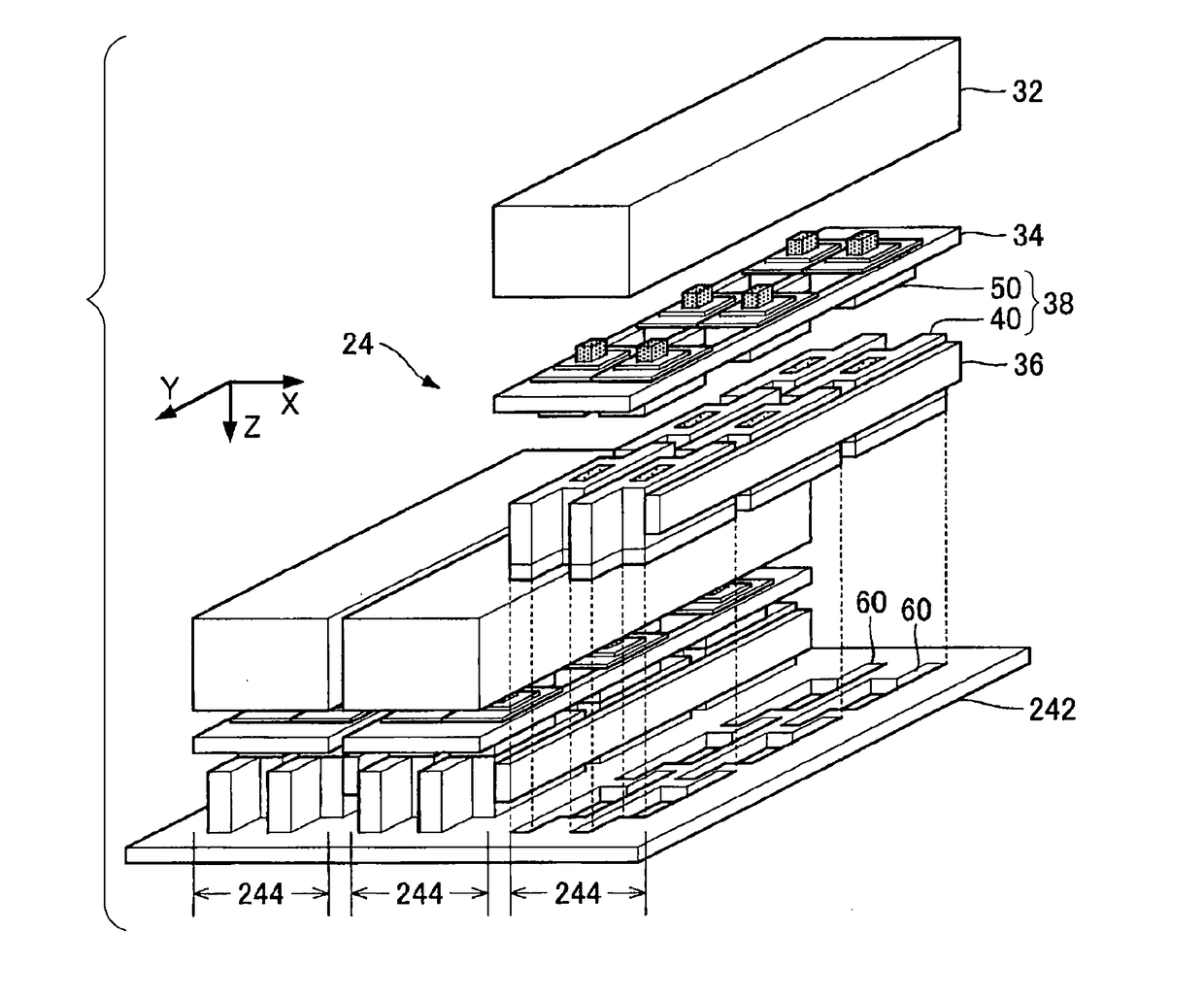
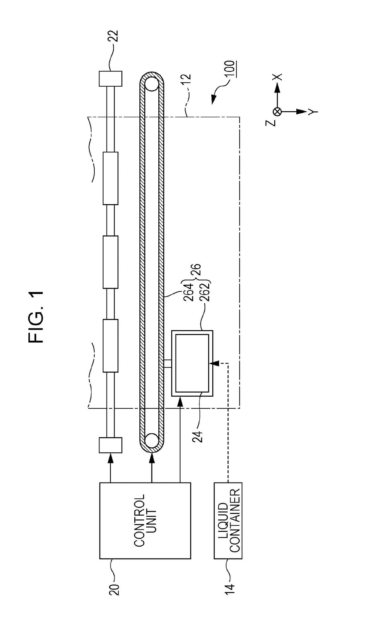
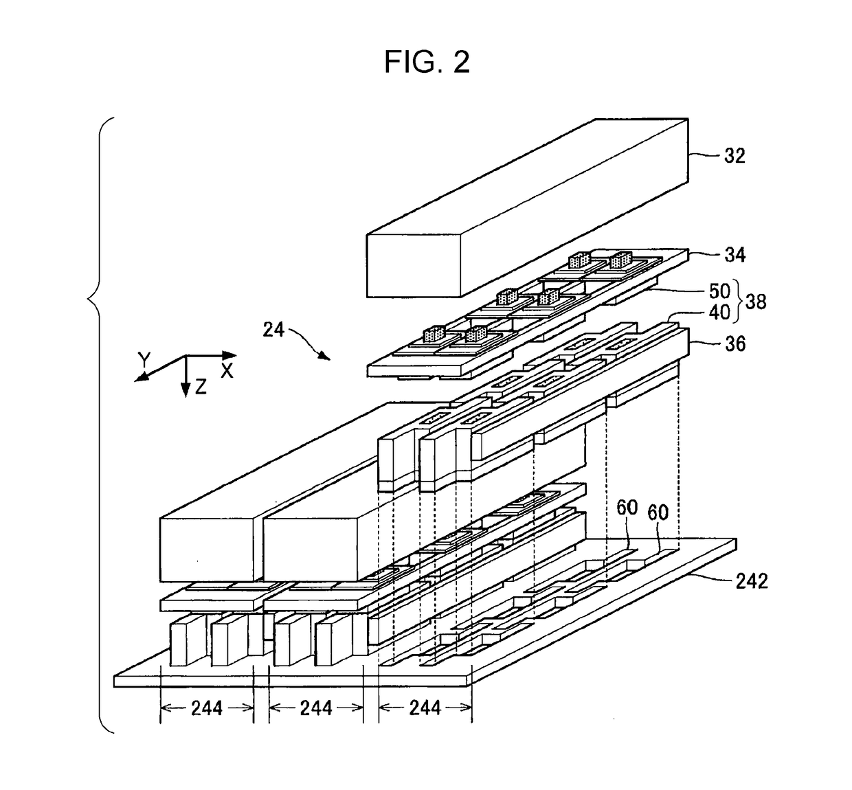
[0045]FIG. 1 is a configuration diagram of a liquid ejecting apparatus 100 according to a first embodiment of the invention. The liquid ejecting apparatus 100 according to the first embodiment is an ink jet type printing apparatus that ejects ink as an example of liquid onto a medium 12. The medium 12 is typically printing paper, but any printing object such as a resin film and a fabric may be used as the medium 12. A liquid container 14 that stores ink is fixed to the liquid ejecting apparatus 100. For example, a cartridge that can be attached and detached to and from the liquid ejecting apparatus 100, a bag-shaped ink pack that is formed by a flexible film, or an ink tank that can supplement ink is used as the liquid container 14. A plurality of types of ink with different colors are stored in the liquid container 14.

[0046]As illustrated in FIG. 1, the liquid ejecting apparatus 100 includes a control unit 20, a transport mechanism 22, and a liquid ejecting head 24. The control uni...

second embodiment

[0118]A second embodiment according to the invention will be described. In each configuration to be described below, elements having the same operation or function as that of the first embodiment are denoted by the same reference numerals used in the description of the first embodiment, and the detailed description thereof will not be appropriately repeated.

[0119]FIG. 23 is an explanatory diagram of the arrangement of the transmission line 56 in the second embodiment. In the first embodiment, as described above with reference to FIG. 6, the configuration in which one end of the transmission line 56 is bonded to the surface of the wiring substrate 544 that is opposite to the connection portion 546 and the other end of the transmission line 56 is bonded to the surface of the wiring substrate 524 that is opposite to the connection portion 526 is illustrated. In the second embodiment, as illustrated in FIG. 23, one end of the transmission line 56 is bonded to the surface of the wiring s...

third embodiment

[0121]FIG. 24 is a partial block diagram of the coupling unit 50 in a third embodiment. In the first embodiment, the connection portion 546 and the liquid ejecting unit 40 are electrically connected to each other by the flexible transmission line 56. In the third embodiment, as illustrated in FIG. 24, the connection portion 546 of the wiring substrate 544 and the connection portion 384 of the liquid ejecting unit 40 are electrically connected to each other by a connection portion 58. The connection portion 58 is a connector (board-to-board connector) having a floating structure, and can absorb the tolerance by the configuration capable of movement to the connection target. Therefore, even in the third embodiment, as in the first embodiment, it is possible to easily assemble or disassemble the liquid ejecting head 24 without considering the stress that is applied from the connection portion 546 to the liquid ejecting unit 40 (further the position deviation of the liquid ejecting unit...


PUM


Abstract

There is provided a liquid ejecting unit that ejects liquid from a plurality of nozzles, in which the planar shape of the ejecting face on which the nozzles are formed is a shape in which a first portion that passes through the center line parallel to the long side of the rectangle of the minimum area including the ejecting face and a second portion that does not pass through the center line are arranged in the direction of the long side.

Description

CROSS-REFERENCE TO RELATED APPLICATIONS[0001]The present application claims priority to Japanese Patent Application No. 2016-017935, filed Feb. 2, 2016, which is hereby incorporated by reference in its entirety.BACKGROUND[0002]1. Technical Field[0003]The present invention relates to a technique for ejecting liquid such as ink or like.[0004]2. Related Art[0005]In the related art, a liquid ejecting head that ejects liquid such as ink or the like from a plurality of nozzles formed on the ejecting face is proposed. For example, in JP-A-2010-179499, a configuration in which a plurality of liquid ejecting heads are fixed to a base plate so as to expose the ejecting face from an opening portion is disclosed.[0006]However, in the technique disclosed in JP-A-2010-179499, since the plurality of liquid ejecting heads are disposed on the base plate in parallel, there is a problem that a reduction in the size of the whole device is limited.SUMMARY[0007]An advantage of some aspects of the inventi...

Claims


Application Information

Patent Timeline
Patent Type & Authority Applications(United States)
IPC IPC(8): B41J2/14
CPCB41J2/1433B41J2/14024B41J2/15B41J2002/14266B41J2202/20B41J2202/19
Inventor KANEGAE, TAKAHIROHAGIWARA, HIROYUKIOKUBO, KATSUHIROSATO, MASAHIKO
Owner SEIKO EPSON CORP
Why Eureka
Try Eureka