Handheld shaker bottle with dispensing cap

a shaker bottle and hand-held technology, applied in the field of dispensing caps, can solve the problems of difficult dispensing of products, and achieve the effect of improving the distribution of particulates

Inactive Publication Date: 2017-08-03
ROSENBAUM NEIL +2
View PDF10 Cites 2 Cited by
  • Summary
  • Abstract
  • Description
  • Claims
  • Application Information

AI Technical Summary

Benefits of technology

[0006]The present invention is a dispensing cap for a container that holds particulate that improves the distribution of particulate from the container. In one embodiment, the dispensing cap comprises a base configured for removable attachment to a mouth of the container and having a port formed therethough for restricting the flow of particulate out of the container and a cover pivotally mounted to the base and moveable between a first position, wherein the cover prohibits particular matter from exiting port of the base and a second position, wherein the cover permits particular matter to exit the post of the base. The base of the dispending cap extends along a first plane defined by the mouth of the container and the cover is coupled to the base via a pivot so that the cover pivots along a second plane that is parallel to the first plane. The cover includes a channel that is misaligned with the port when the cover is in the first position and is aligned with the port of the base when the cover is in the second position. The cover may also be dimensioned to extend beyond the container to which base is attached when it is in the second position. The cover can include a series of ribs extending from a first position positioned proximately to the mouth of the container to a second portion positioned proximately to a peripheral edge of the cover. The series of ribs define a path for the flow of particulate that is parallel to the first plane. The cover may further include a dimple positioned between the series of ribs to redirect particulate that flows from the mouth of the container and across the cover.

Problems solved by technology

Even if the container has a handle, dispensing product can be difficult as the container must be held in an unnatural position.

Method used


Image

  • Handheld shaker bottle with dispensing cap
  • Handheld shaker bottle with dispensing cap
  • Handheld shaker bottle with dispensing cap

Examples


first embodiment

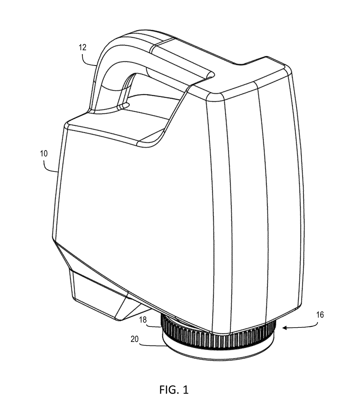
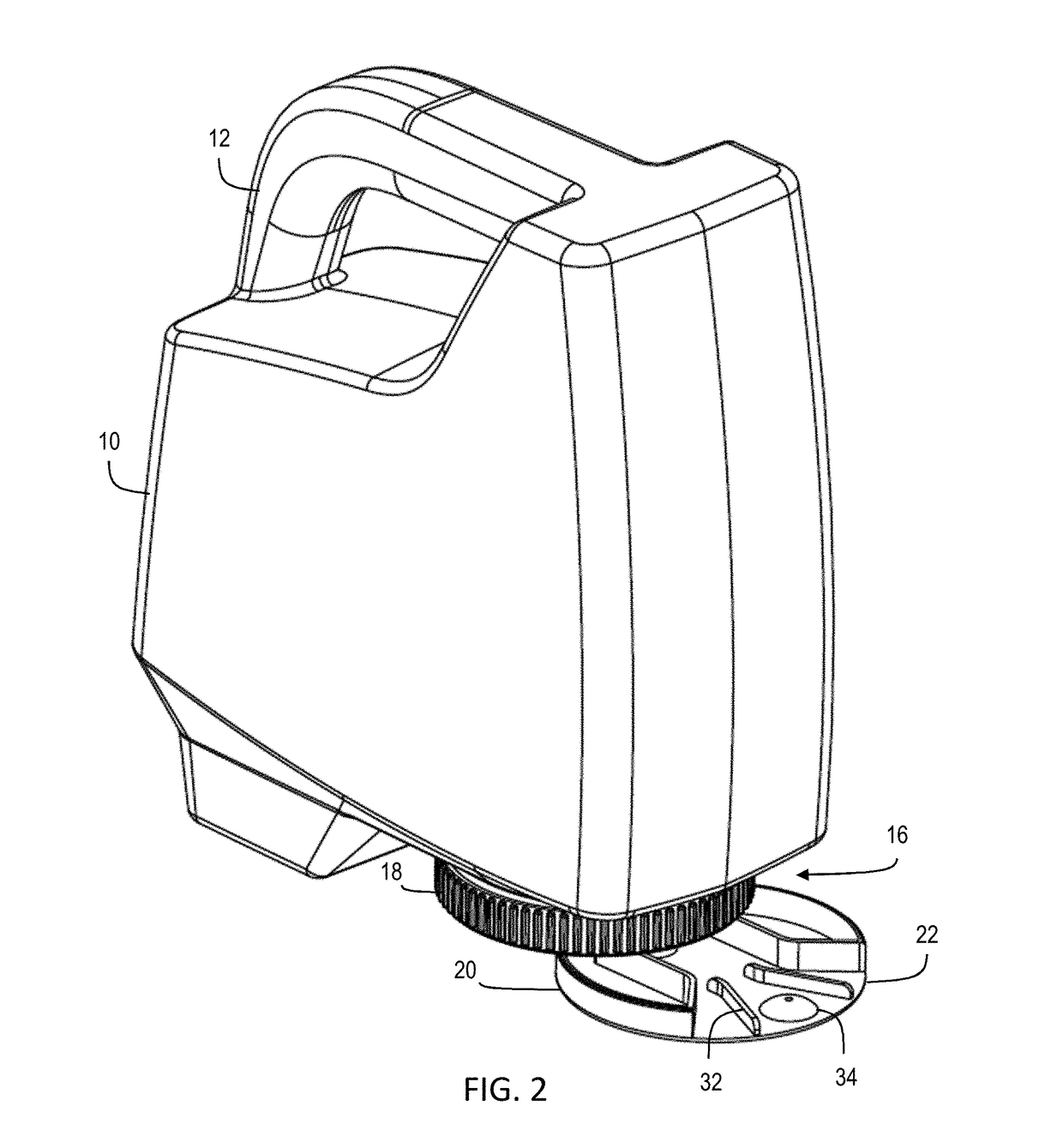
[0021]Referring to FIG. 2, in a first embodiment, cover 20 of dispensing cap 16 comprises a disk 22 coupled to base 18 by a pivot 36. As seen in FIG. 5, base 18 includes a body 24 defining a port 26 formed therethrough that is dimensioned to regulate the amount of particulate that can flow to cover 20. Disk 22 includes a first portion 28 that blocks port 26 when cover 20 in the closed position, and a channel 30 that is in communication with port 26 when cover 20 in in the open position. As seen in FIGS. 2 and 4, disk 22 is pivotal through a plane that is parallel to the plane of body 24 of base 18 to extend outwardly from container 10. Disk 22 further includes a series of ribs 32 and a central dimple 34 positioned along the plane of disk 22 that are in communication with channel 30 to guide particulate flowing through port 26 across the exposed width of cover 20 and thus improve dispersal. Cover 20 may be thus moved between a first position, as seen in FIGS. 1 and 3, where cover 20 ...

second embodiment

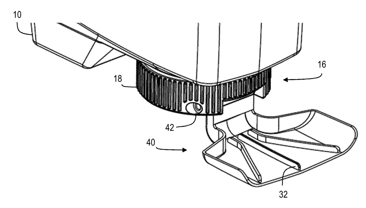
[0022]Referring to FIGS. 6 through 8, in a second embodiment, cover 20 may comprise an L-shaped scoop 40 pivotally mounted to base 18 for movement between a closed position where scoop 40 is held closely along the bottom and side of container 10, and an open, dispensing position, where scoop 40 extends outwardly from container 10. Referring to FIG. 10, hinge 42 for scoop 40 is formed from a concave cavity 44 that extends laterally across base 18 and a barrel 46 formed in the hinge end of scoop 40 that is positioned with cavity 44 of base 18. Cavity 44 has a slot 48 formed through its inner wall that is in communication with opening 14 so that particulate can pass through opening 14 and then through slot 48. Barrel 46 of scoop 40 includes a corresponding slot 50 formed therethrough that is positioned to align with slot 46 of cavity 44 only when scoop 40 is in the open or deployed position, thereby allowing material to flow out of container 10 through slot 48 and slot 50 and across on...


PUM


Abstract

A handheld container for dispensing particulate matter having an opening and a moveable cover for the opening positioned at the bottom of the container. The cover has a pivoting lid that can selectively open or close the opening of the container and assist with dispersal of particulate from the container while a user holds the container in an upright position. The lid may swing outward from the container or hinge into an open position and include a series of ribs for improving the dispersal of particulate.

Description

CROSS-REFERENCE TO RELATED APPLICATIONS[0001]The present application claims priority to U.S. Provisional Application No. 62 / 290,024 filed on Feb. 2, 2016.BACKGROUND OF THE INVENTION[0002]1. Field of the Invention[0003]The present invention relates to particulate containers and, more specifically, to a a dispensing cap for manually dispensing particular from the container.[0004]2. Description of the Related Art[0005]Granular products, such as fertilizer and ice melting chemical, are typically dispensed from handheld containers by inverting the bottle, opening the cap of the container, and then shaking the container to distribute particular from the opening of the bottle. Even if the container has a handle, dispensing product can be difficult as the container must be held in an unnatural position. Accordingly, there is a need in the art for a dispensing system that is easier to use.BRIEF SUMMARY OF THE INVENTION[0006]The present invention is a dispensing cap for a container that holds...

Claims


Application Information

Patent Timeline
Patent Type & Authority Applications(United States)
IPC IPC(8): B65D47/04B65D83/06B65D25/28B65D47/08
CPCB65D47/046B65D47/043B65D25/2894B65D83/06B65D47/089B65D47/265B65D47/305
Inventor ROSENBAUM, NEILMARCONI, FREDRYAN, SCOTT
Owner ROSENBAUM NEIL
Why Eureka
Try Eureka