Electrically powered hand spreader

a hand spreader and electric motor technology, applied in the field of electric hand spreaders, can solve the problems of many of the same drawbacks, poor distribution and control of dispensing, and a lot of contact between the user and the system, and achieve the effects of less contact with particulate matter, easy replenishment or reuse, and less cos

Active Publication Date: 2015-12-29
MARCONI FRED
View PDF15 Cites 2 Cited by
  • Summary
  • Abstract
  • Description
  • Claims
  • Application Information

AI Technical Summary

Benefits of technology

[0006]It is therefore a principal object and advantage of the present invention to provide a powered handheld spreader that has improved particulate distribution.
[0007]It is an additional object and advantage of the present invention to provide a powered handheld spreader that minimizes contact with particulate.
[0008]It is a further object and advantage of the present invention to provide a powered handheld spreader that is less expensive and may be easily replenished or reused.
[0009]It is also an object and advantage of the present invention to provide a powered handheld spreader that is easy to manufacture and can be filled with particulate during the assembly process.
[0010]In accordance with the foregoing objects and advantages, the present invention provides a handheld spreader having a fillable container that is interconnected to a base assembly having a blower and air flow channel via a slide having a vibrating eccentric plate for guiding particular matter and improving flow of particulate into channel. Particulate dispensed from the container is collected in the air flow channel and distributed out of the spreader. The container and base are further interconnected by a coupling member that frictionally engages and seals the container to the base, thereby allowing for easy assembly of spreader, including assembly after container has been filled with particulate as well as easy reassembly if container is removed and refilled at a later date. The spreader further comprises a sliding gate that may be operated by a user to open and close the opening of the container while simultaneously activating and deactivating the blower motor.BRIEF DESCRIPTION OF THE SEVERAL VIEWS OF THE DRAWING(S)

Problems solved by technology

These systems typically have poor distribution and control over dispensing, and require that the user physically drive spreading operations by moving along the ground or turning a crank.
These systems also require a lot of contact between the user of the system and the particulate to be spread, which is a significant disadvantage due to the hazardous nature of many particulates.
While automatically powered spreaders avoid the need for the user to provide the distributing force, they suffer from many of the same drawbacks.
For example, electrically powered spreader plates still have poor distribution and control, due in part to the lack of means for ensuring flow of particular from the container to the distributor, and also require that the user manually handle particulate.
Other systems, such as those the attached to conventional leaf blowers are mechanically complicated and expensive.
While these systems may be attractive to commercial customers, they are not too expensive and complicated for the average homeowner and require the use of additional equipment that is expensive and difficult to use.

Method used


Image

  • Electrically powered hand spreader
  • Electrically powered hand spreader
  • Electrically powered hand spreader

Examples


Embodiment Construction

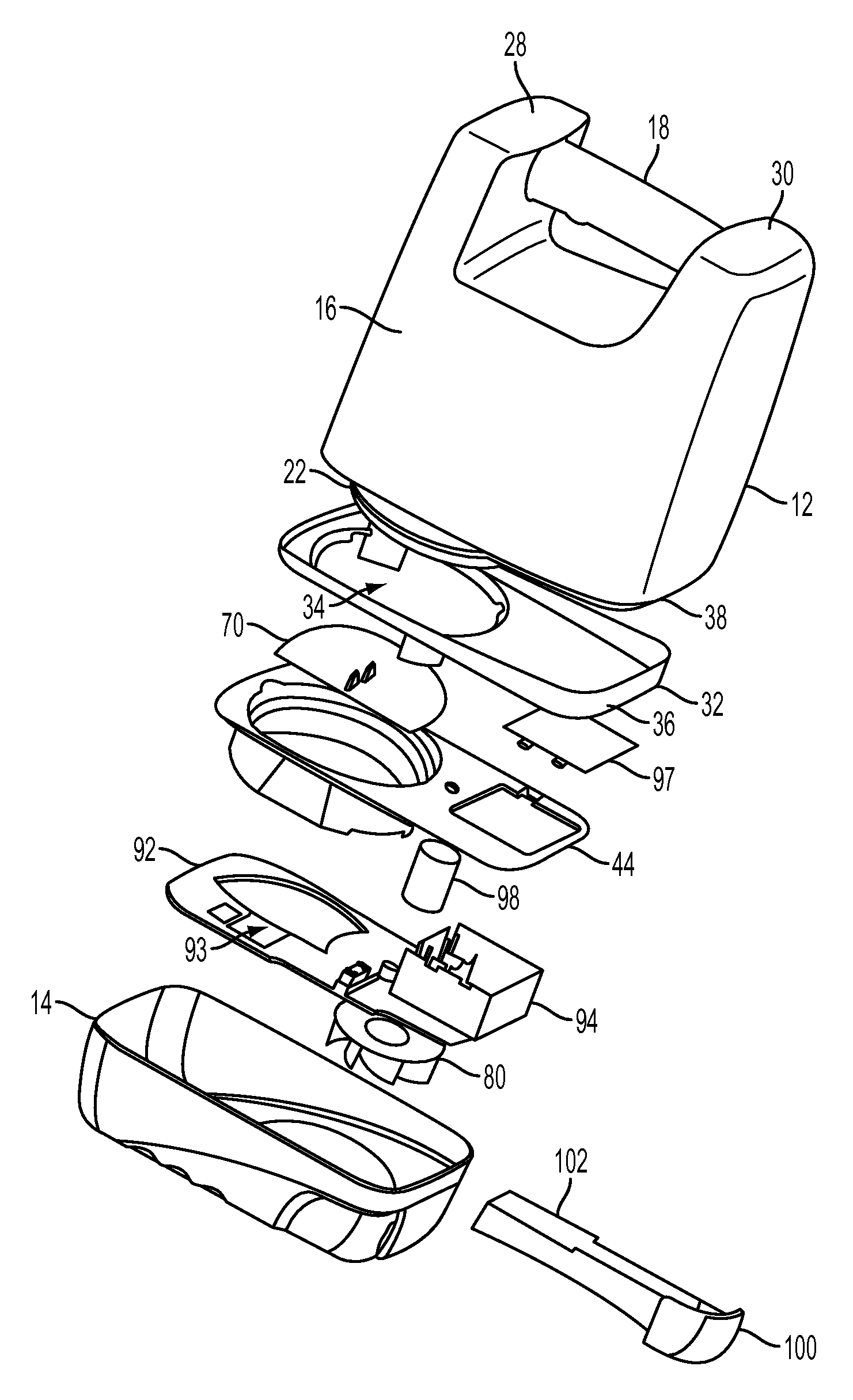
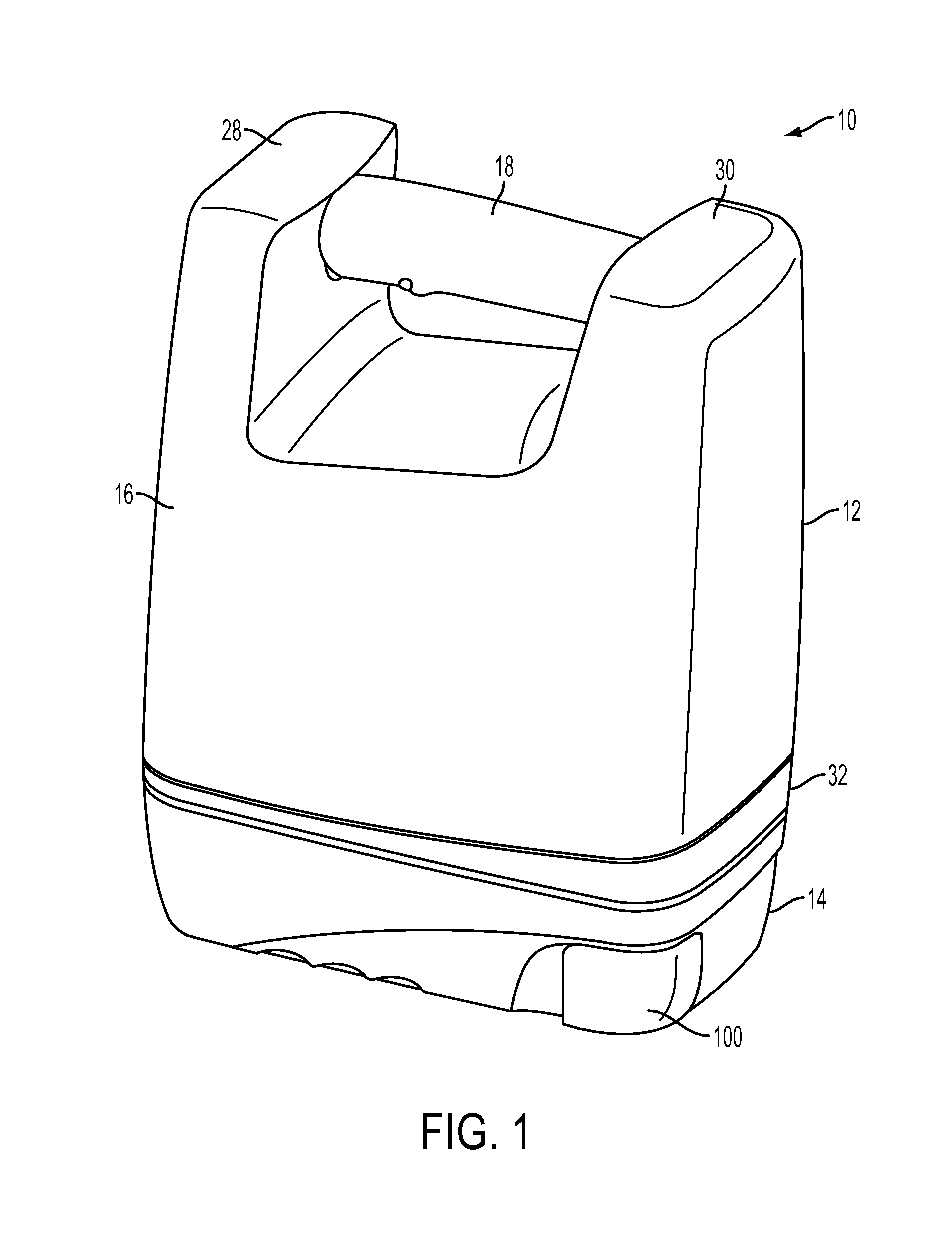
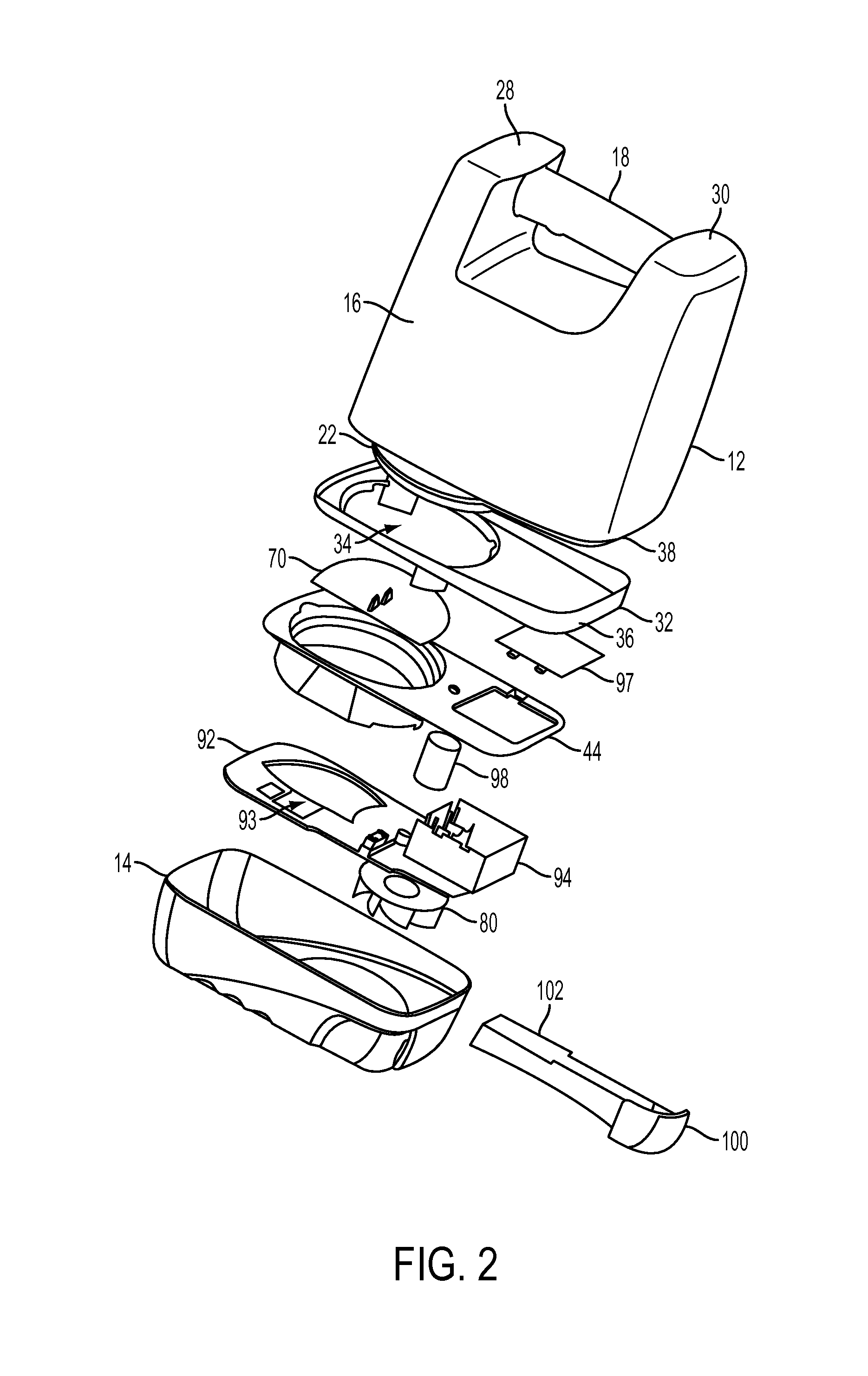
[0023]Referring now to the drawings, wherein like reference numerals refer to like parts throughout, there is seen in FIG. 1 a powered hand spreader 10 according to the present invention. Spreader 10 comprises an upper assembly having a container 12 that may be selectively attached to or detached from a bottom assembly comprising a base 14.

[0024]Container 12 comprises an upper housing 16 having a user handle 18 and defining a cavity 20 therein for holding particulate matter therein. As seen in FIG. 4, container 12 further includes a tubular chute 22 extending outwardly therefrom and having a series of circumferentially extending external ridge 24. Tubular chute 22 defines an opening 26 in the bottom of container 12 that allows any particulate in cavity 20 to be a gravity fed out of container 12 through opening 26. It should be recognized by those of skill in the art that opening 26 may be temporarily covered by a foil or other closure to ensure that any potentially harmful particula...


PUM


Abstract

A handheld spreader having a fillable container for dispensing particulate from an electrically powered blower assembly in a detachable base. The spreader includes a feed slide leading from the container to the air stream channel of the base that has a vibrating eccentric plate for guiding and improving the flow of particulate from container into the air stream. The container and base are frictionally engaged together, thereby allowing for easy assembly of spreader, including assembly after container has been filled with particulate, as well as easy reassembly if container is removed and refilled. The spreader includes a rotating slide that may be operated by a user to open and partially close the feed slide of the container to control the feed rate.

Description

BACKGROUND OF THE INVENTION[0001]1. Field of the Invention[0002]The present invention relates to particulate spreading devices and, more particularly, to an electrically powered hand spreader.[0003]2. Description of the Related Art[0004]Home owners frequently need to dispense particulate matter, such as lawn fertilizer, weeding chemicals, grass seed, and even salt, over a given area, such as lawn, sidewalk or driveway. Conventional methods for spreading or dispensing particulate have a hopper that is manually filled particulate and allows the particulate to gravity feed onto a spinning spreader plate that cases the particulate outwardly. The spreader is usually powered by mechanical interconnection to wheels or a hand crank associated with the spreader plate so that the plate is causes to spin and the user pushes the hopper along the ground or turns the hand crank. These systems typically have poor distribution and control over dispensing, and require that the user physically drive ...

Claims


Application Information

Patent Timeline
Patent Type & Authority Patents(United States)
IPC IPC(8): A01M9/00E01H10/00A01C7/02A01C15/02
CPCE01H10/00A01M9/0046A01C15/02A01C7/02
Inventor MARCONI, FRED
Owner MARCONI FRED
Why Eureka
Try Eureka