Damping Valve Comprising A Pressure Relief Valve
a technology of pressure relief valve and dripping valve, which is applied in the direction of functional valve types, shock absorbers, mechanical devices, etc., can solve the problem that the dripping orifice may not be sufficien
- Summary
- Abstract
- Description
- Claims
- Application Information
AI Technical Summary
Benefits of technology
Problems solved by technology
Method used
Image
Examples
Embodiment Construction
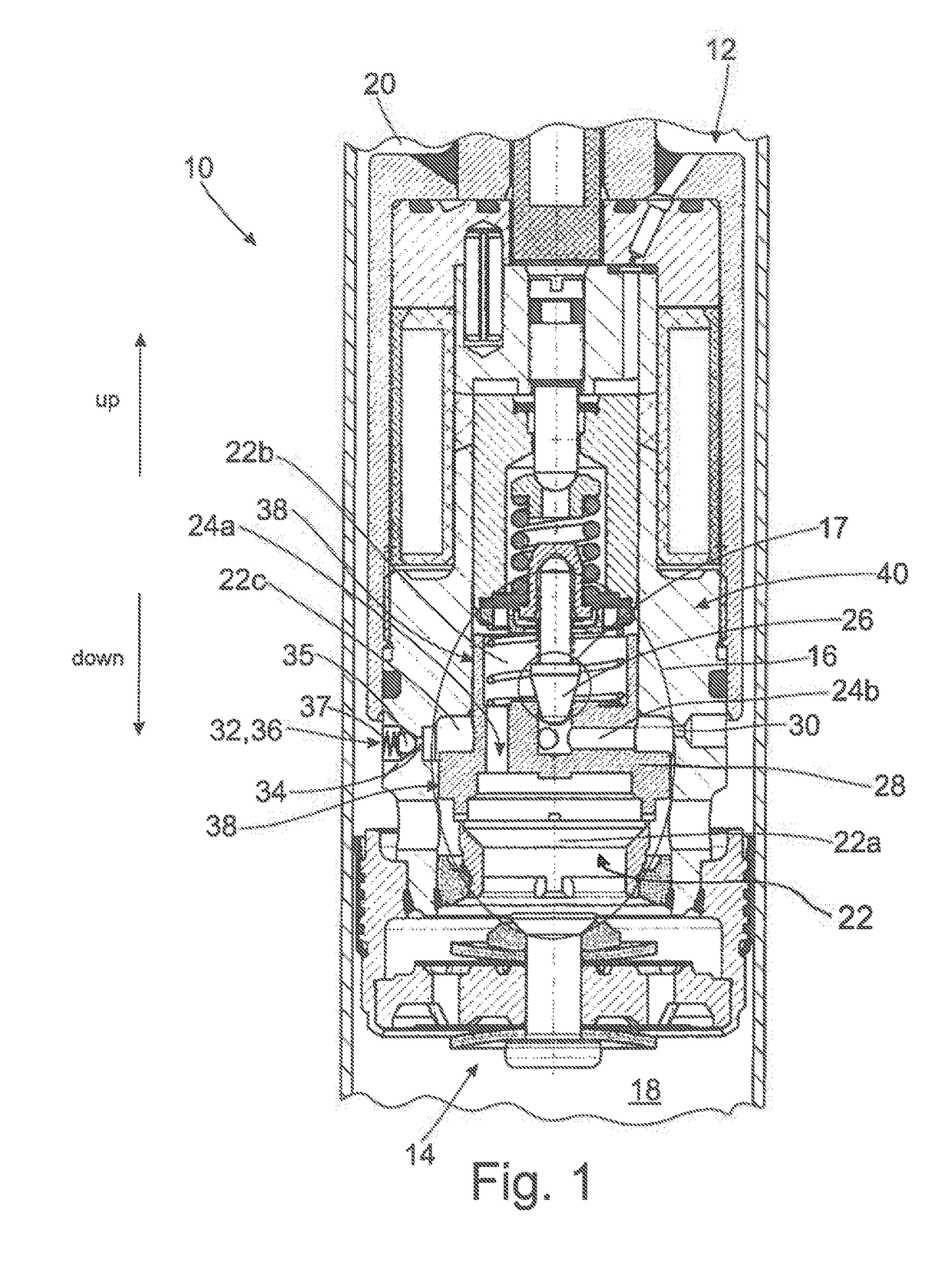
[0020]The directions “up” and “down” are shown in FIG. 1 and are used in the following for purposes of illustration.
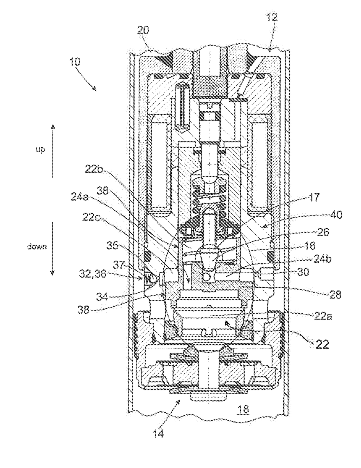
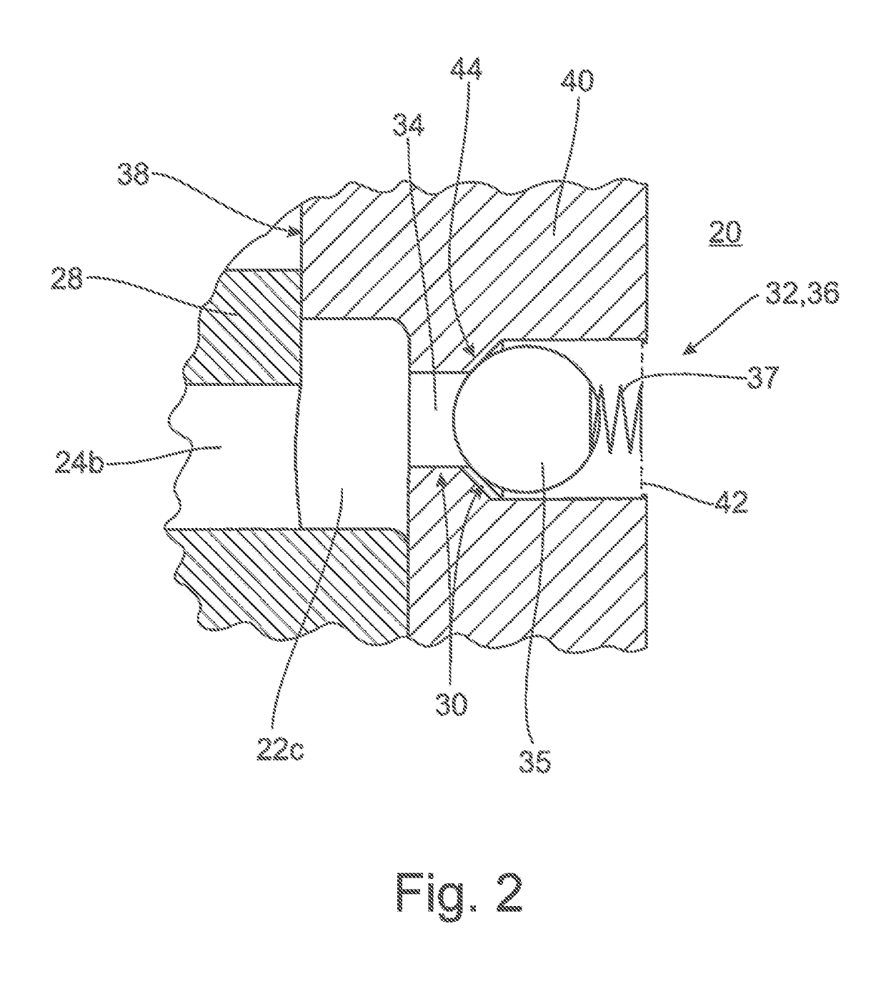
[0021]FIG. 1 shows a cross section of a vibration damper 10 with an adjustable damping valve 12. The damping valve comprises an inlet valve 14, which is optional in this case, and an adjustable main valve 16 with a pre-valve 17. While the damping valve 12 separates a lower working space 18 from an upper working space 20, the main valve 16 divides the interior 22 into a plurality of partial spaces, including a main space 22a, a feed space 22b and a control space 22c. In the preceding as well as in the following, the control space 22c is also designated as pressure space 22c. The main space 22a and the feed space 22b are connected to one another via a channel 24a in a main valve body 28. Further, when a valve cone 26 of the pre-valve 17 lifts from the main valve body 28, a connection is made or blocked between the feed space 22b and the control space 22c via a further ch...
PUM
 Abstract
Description
Claims
Application Information
 - R&D
- Intellectual Property
- Life Sciences
- Materials
- Tech Scout
- Unparalleled Data Quality
- Higher Quality Content
- 60% Fewer Hallucinations
Browse by: Latest US Patents, China's latest patents, Technical Efficacy Thesaurus, Application Domain, Technology Topic, Popular Technical Reports.
© 2025 PatSnap. All rights reserved.Legal|Privacy policy|Modern Slavery Act Transparency Statement|Sitemap|About US| Contact US: help@patsnap.com


