
Spin Point for Archery Arrows

a technology of archery arrows and pin points, which is applied in the field of archery, can solve the problems of not being identical in weight and size to each other, being too light weight to shoot from some bows, and being expensive,

Inactive Publication Date: 2017-08-03
GIZOWSKI JEROME EDWARD +1
View PDF3 Cites 2 Cited by
  • Summary
  • Abstract
  • Description
  • Claims
  • Application Information

AI Technical Summary

Benefits of technology

The present invention is a spinning point that is mounted to the end of an arrow and allows the cutting tip or arrowhead to spin or rotate while in flight and when contact is made with the target. This results in greater penetration and quicker and more humane kills. The spinning point is easy to install, allows for faster spinning and better accuracy down range. It also results in no arrowhead planing and allows for better flight and accuracy of the projectile. The spinning point can be any type of tip or arrowhead known in the art and is attached to the arrow shaft in a way that allows it to spin or rotate independently of the shaft. This results in better accuracy and a flatter flight path.

Problems solved by technology

Carbon shafts have the advantage that they do not bend or warp, but they can often be too light weight to shoot from some bows and are expensive.
Wood shafts are the least expensive option but often will not be identical in weight and size to each other and break more often than the other types of shafts.
However, it often occurs that the individual doesn't develop the requisite strength and thus when hunting exerts too little (pull) draw weight on the bow so that when the target is struck the arrow doesn't achieve sufficient penetration to the vitals of the game animal.
In addition, the energy and lethality of the arrow is immediately diminished upon striking bone.
Thus, the arrow must cut or break bone to reach the animal's vitals, and this results in the game animal being wounded but not quickly killed.
As applied to target archery, the lack of strength results in the arrow not achieving sufficient velocity and being adversely effected by wind resistance or other factors, thereby effecting the distance and accuracy of the shot.
The flight of prior art points is adversely affected by wind resistance acting against them, making it more difficult to effectively hit a target.
U.S. Pat. No. 7,207,908 discloses an insert for allowing free rotation of a cutting tip on an arrow shaft, but does not teach or suggest the presently claimed spinning point.
Differences in the aerodynamics of points renders much of the prior art inapplicable.

Method used


Image

  • Spin Point for Archery Arrows
  • Spin Point for Archery Arrows
  • Spin Point for Archery Arrows

Examples


Embodiment Construction

[0061]Various embodiments of the invention are described more fully hereinafter with reference to the accompanying drawings. Some, but not all, embodiments of the invention are shown in the figures. Indeed, the disclosed invention may be embodied in many different forms and should not be construed as limited to the embodiments set forth herein. Rather, these embodiments are provided as examples, and so that this disclosure will satisfy legal requirements.

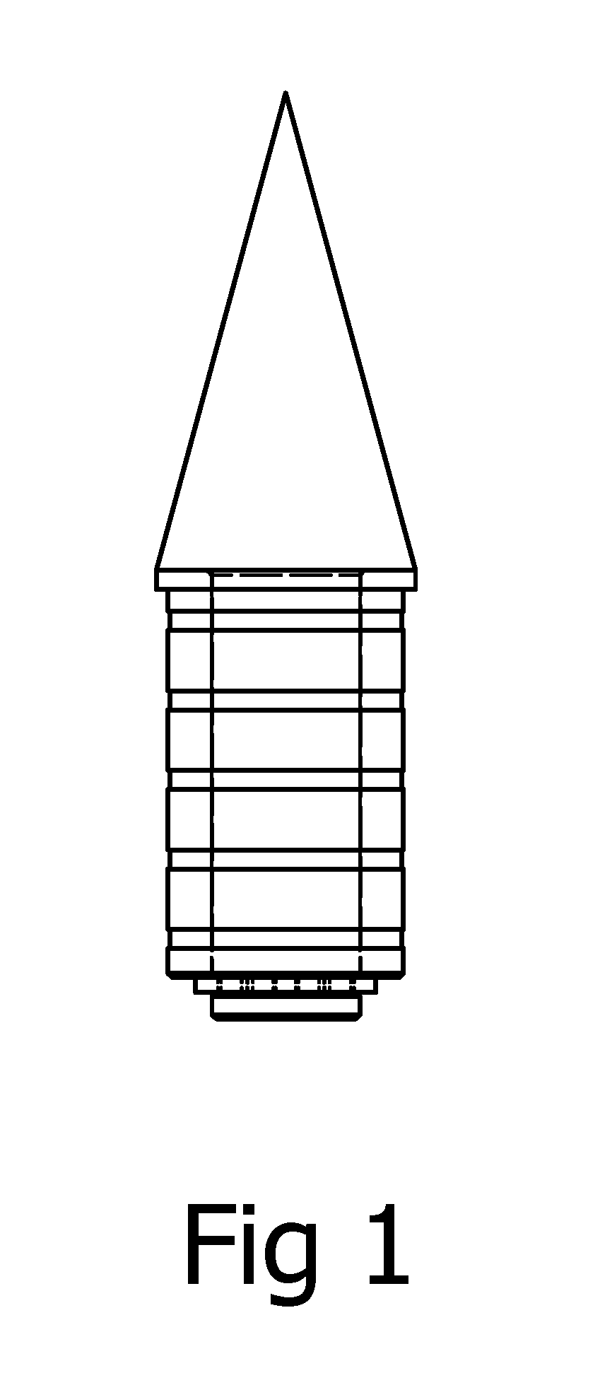
[0062]A first embodiment of the present invention is shown in FIG. 1. FIG. 1 shows a spinning point 1 that is removably attachable to the shaft of an arrow, and that allows the spinning point to freely spin or rotate relative to the rotation of the shaft of the arrow when the arrow is in flight and upon impact with the target. FIG. 1 shows the unitary Main body of the arrowhead 8 and stem 11, the sleeve 15 disposed upon the stem 11, and the clip 16 disposed in the annular groove 14.

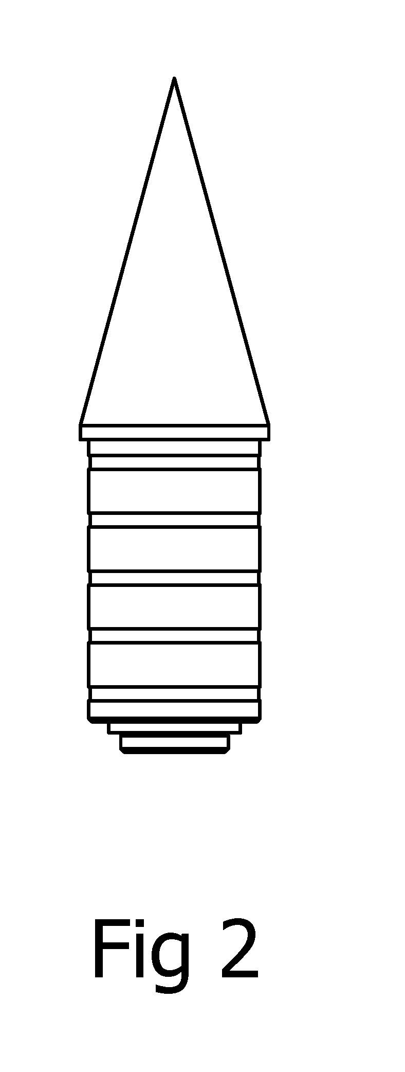
[0063]FIG. 2 shows spinning point 1 that is removab...


PUM


Abstract

A spinning point for an arrow which is rotatable independently from an arrow shaft to which it is connected. The point has an arrowhead and a sleeve, with the arrowhead and the sleeve axially aligned, and the arrowhead has a main body and a stem which are a unitary element. The stem has a diameter less than the diameter of the second end of the main body of the arrowhead, and extends from the second end of the main body of the arrowhead. The sleeve is cylindrical and is disposed about the stem, and is secured to the stem with a clip. The sleeve is dimensioned to allow it to be slipped over the stem of the arrowhead. The stem and the arrowhead are capable of spinning or rotating together relative to the sleeve and the arrow.

Description

CROSS-REFERENCE TO RELATED APPLICATIONS[0001]This application claims the benefit of U.S. Provisional Application No. 62 / 388,458, filed Feb. 1, 2016.STATEMENT REGARDING FEDERALLY SPONSORED RESEARCH OR DEVELOPMENT[0002]Not ApplicableREFERENCE TO SEQUENCE LISTING, A TABLE, OR A COMPUTER PROGRAM LISTING COMPACT DISK APPENDIX[0003]Not ApplicableBACKGROUND OF THE INVENTION[0004]1. Field of the Invention The present invention relates to the field of archery. More particularly, the present invention relates to spinning point securable to the tip end of an arrow for allowing the point to independently rotate relative to the arrow both when the arrow is in flight and when contact is made with the target.[0005]2. Background of the Invention[0006]The bow and arrow is a projectile weapon system that predates written history. The bow is a flexible arc which shoots aerodynamic projectiles called arrows. Generally, the two ends of the bow are joined together with a string such that when the string ...

Claims


Application Information

Patent Timeline
IPC IPC(8): F42B6/08
CPCF42B6/08
Inventor GIZOWSKI, JEROME EDWARDGIZOWSKI, FREDERICK SCOTT
Owner GIZOWSKI JEROME EDWARD
Learn More