

Patterned ground shield
Patent Information
- Authority / Receiving Office
- US · United States
- Patent Type
- Applications(United States)
- Current Assignee / Owner
- REALTEK SEMICON CORP
- Publication Date
- 2017-08-03
Smart Images
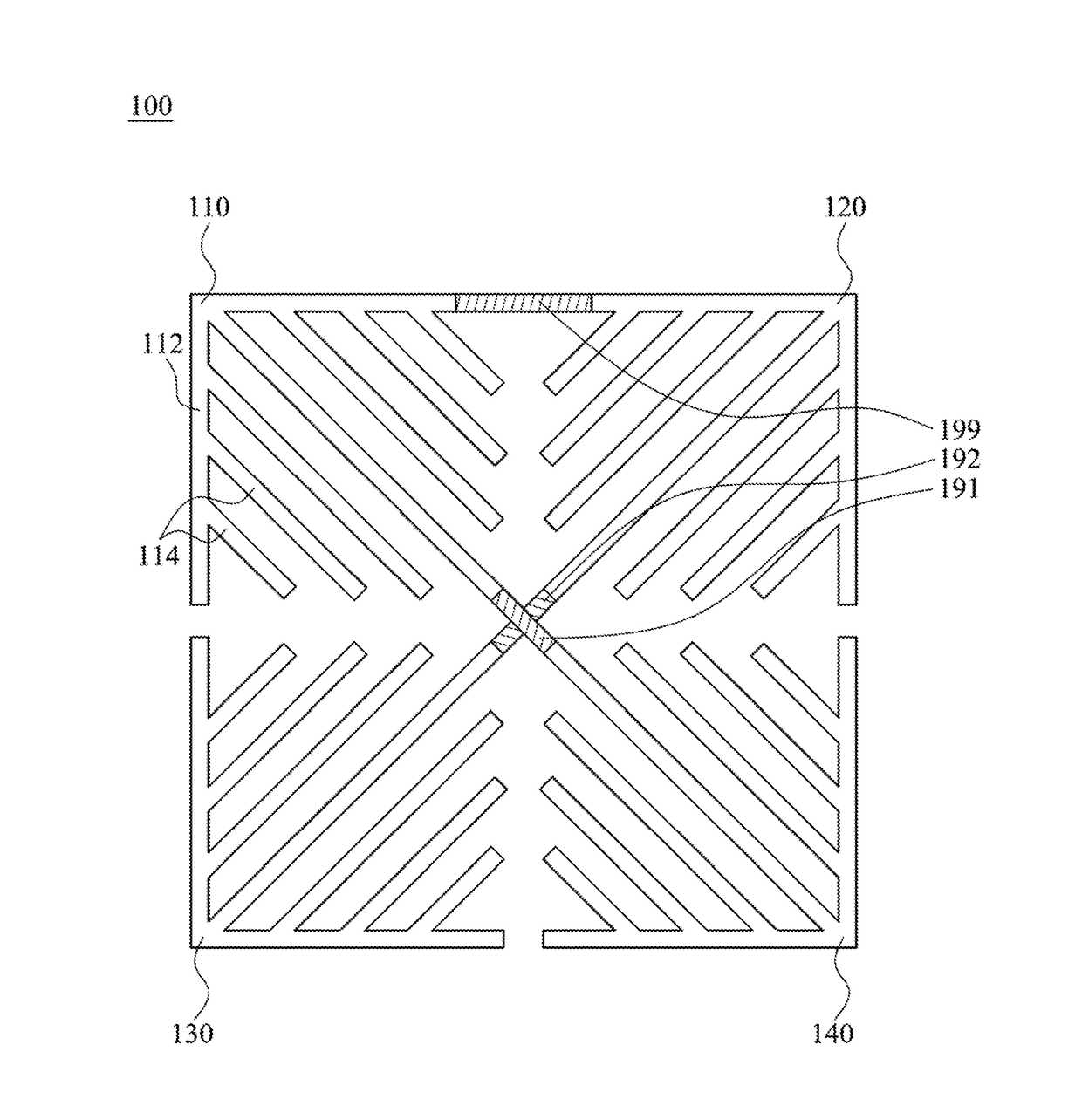
Figure 1 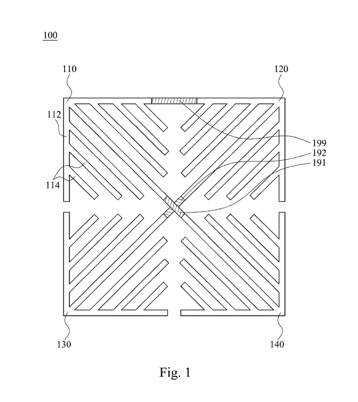
Figure 2 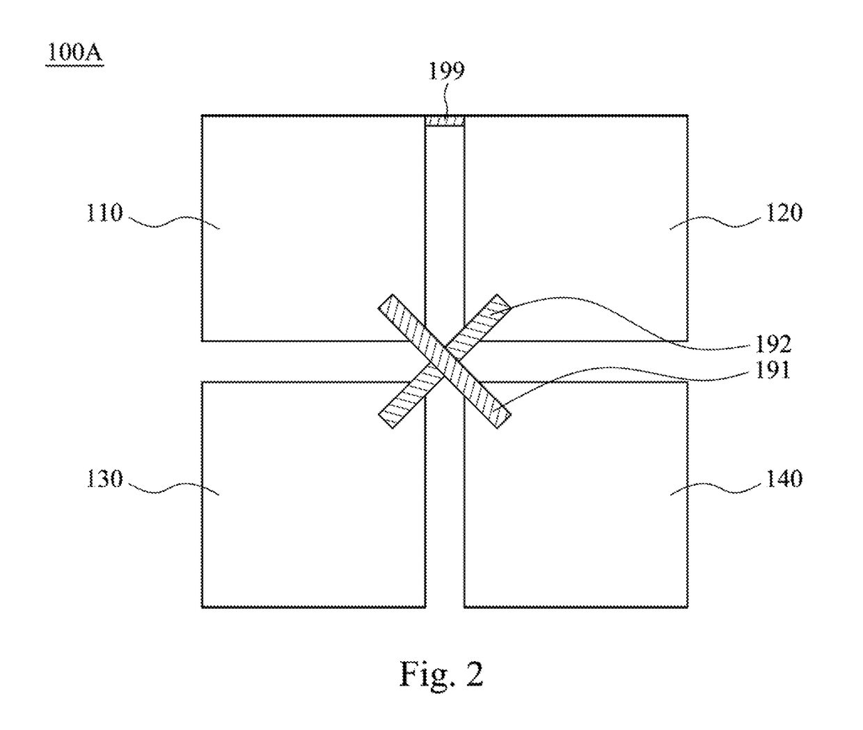
Figure 3
Abstract
Description
RELATED APPLICATIONS
[0001] This application claims priority to Taiwan Application Ser. No. 105102673, filed Jan. 28, 2016, which is herein incorporated by reference.BACKGROUND
[0002] Field of Invention
[0003] The present disclosure relates to basic electronic elements. More particularly, the present disclosure relates to a patterned ground shield.
[0004] Description of Related Art
[0005] With advances in technology, manufacturing processes of integrated inductors are developing toward 28 nm and 20 nm. Such extremely small dimensions of integrated inductors, however, are the cause of a number of negative effects. For example, the capacitance thereof is high since the oxide layer of the integrated inductor is thin, the capacitance among redistribution layers (RIX) is high since the RDLs employed in the integrated inductor is thick, and so on. Such situations affect the quality factor of inductors.
[0006] In view of the foregoing, problems and disadvantages are associated with existing products t...