Method and apparatus for directional skin tightening

a skin tightening and directional technology, applied in the field of directional skin tightening, can solve the problems of small improvement, present-day non-invasive skin tightening techniques only deliver small improvemen

Active Publication Date: 2017-08-10
LUMENIS BE LTD
View PDF2 Cites 0 Cited by
  • Summary
  • Abstract
  • Description
  • Claims
  • Application Information

AI Technical Summary

Benefits of technology

[0010]In a further aspect, the skin tissue treated is one or more wrinkles or other imperfections and the step of squeezing or stretc

Problems solved by technology

Present day non-invasive skin tightening techniqu

Method used


Image

  • Method and apparatus for directional skin tightening
  • Method and apparatus for directional skin tightening
  • Method and apparatus for directional skin tightening

Examples


Embodiment Construction

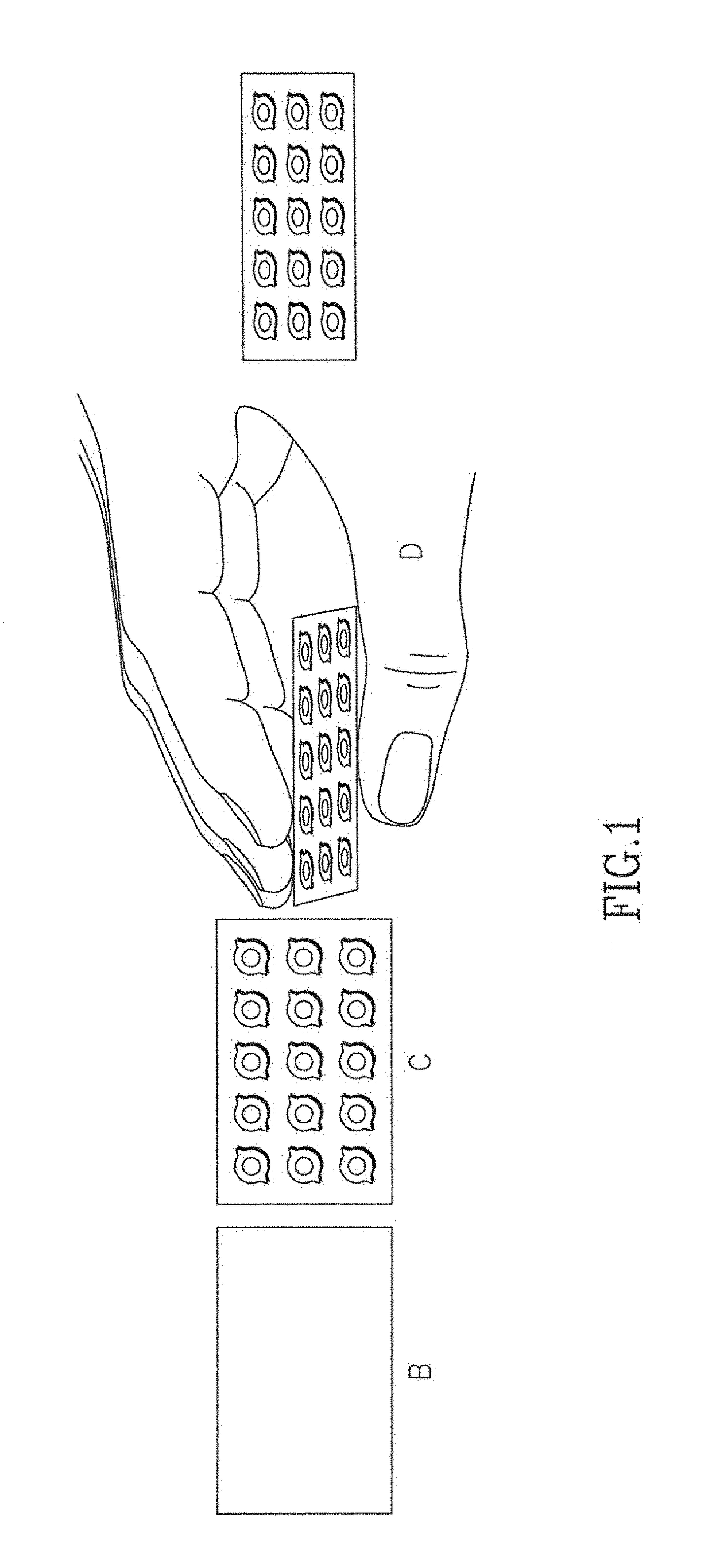
[0020]The welding discussed above may be achieved in a directional manner, by way of example only, by an operator physically pushing, squeezing or otherwise manipulating the skin in one direction of an array of fractional ablated holes, and then applying the second laser source to weld and hold this shape, as may be see in FIG. 1. Several studies have shown that laser assisted tissue bonding (LTB) offers a fast and efficient method for full-thickness macroscopic incision closure, which diminishes scar formation. Examples in the literature include the following:[0021]Fried N M, Walsh J T Jr. Laser skin welding: in vivo tensile strength and wound healing results. Lasers Surg Med. 2000; 27(1):55-65; Simhon D, Halpern M, Brosh T, Vasilyev T, Ravid A, Tennenbaum T, Nevo Z, Katzir A. Immediate tight welding of skin incisions using an innovative temperature-controlled laser soldering device: in vivo study in porcine skin. Ann Surg. 2007 February; 245 (2):206-13; Ahmed A. Abbood Human Skin ...


PUM


Abstract

A cosmetic method of directionally tightening human skin tissue includes providing an ablative laser source and a non-ablative laser source, then using the ablative laser source to form one or more overlapping circular shaped microchannels in the skin tissue; the overlapping microchannels formed have a longitudinal dimension larger than their cross dimension; then, using the non-ablative laser source to weld the microchannels, whereby the welding causes the skin tissue to tighten.

Description

RELATED APPLICATION[0001]This application is related to and claims priority to U.S. provisional application Ser. No. 62 / 291,796, filed Feb. 5, 2016, the entire contents of which are herein incorporated by reference.BACKGROUND[0002]Present day non-invasive skin tightening techniques only deliver small, millimeters of improvement. By contrast, in an invasive procedure, such as a facelift, typically larger, centimeters of improvement are experienced. Directional skin tightening is commonly known in that one can shape the skin with a skin compression technique in which the skin would generally be expected to hold its shape.SUMMARY OF THE PRESENT INVENTION[0003]Herein it is suggested achieving directional shrinkage of the skin by combining two different mechanism of actions induced by two lasers sources: an ablative laser (such as, for example, an Erbium laser working at a wavelength of about 2.9 μm (about 2940 nm) or a CO2 laser working at wavelength of about 10.6 μm (about 10,600 nm)) ...

Claims


Application Information

Patent Timeline
IPC IPC(8): A61B18/20
CPCA61B18/203A61B2018/00577A61B2018/2015A61B2018/00452A61B2018/00619A61B2018/0047A61B2018/00589
Inventor CHOYE, RAYMONDGREENBAUM, LIOR
Owner LUMENIS BE LTD
Why Eureka
Try Eureka