
Auto-Injector with Pivoting Trigger

a technology of auto-injector and trigger, which is applied in the direction of ampoule syringes, intravenous devices, needles infusion, etc., can solve the problem of no safety mechanism to prevent users, and achieve the effect of easing the anxiety of users

Active Publication Date: 2017-08-10
SHL MEDICAL AG
View PDF1 Cites 4 Cited by
  • Summary
  • Abstract
  • Description
  • Claims
  • Application Information

AI Technical Summary

Benefits of technology

The patent describes a medicament injection device that includes a trigger mechanism. The trigger mechanism includes a button or trigger that can pivot between a cocked position and a fired position. The device also includes a button blocker that can slide from a blocked position to a release position, allowing the button to move from the cocked position to the fired position. The device also includes a plunger rod driver that is engaged by a catch on the button. The catch prevents the button from moving from the cocked position to the fired position until the catch disengages from the catch. The device also includes a needle hider that can be adjusted to control the axial position of the needle, and a syringe guide that can be adjusted to control the insertion depth of the needle shield remover. The technical effects of the invention include improved trigger mechanisms and easier adjustment of the needle hider and syringe guide.

Problems solved by technology

Drawbacks with prior known device is that once the trigger is cocked there is no safety mechanism to prevent a user from accidentally pushing the trigger and firing the device before the auto-injector has been placed against an injection site.

Method used


Image

  • Auto-Injector with Pivoting Trigger
  • Auto-Injector with Pivoting Trigger
  • Auto-Injector with Pivoting Trigger

Examples


Embodiment Construction

[0029]As used herein, the term “container” encompasses all types of containers suitable for injectable liquid composition. Concerning the terms “distal” and “proximal” they refer to points that are closer to and further away from the injection site, respectively. So, for example, the needle hider of the reusable auto-injection device described herein is located at the distal end of the injector and the trigger is located at the proximal end.

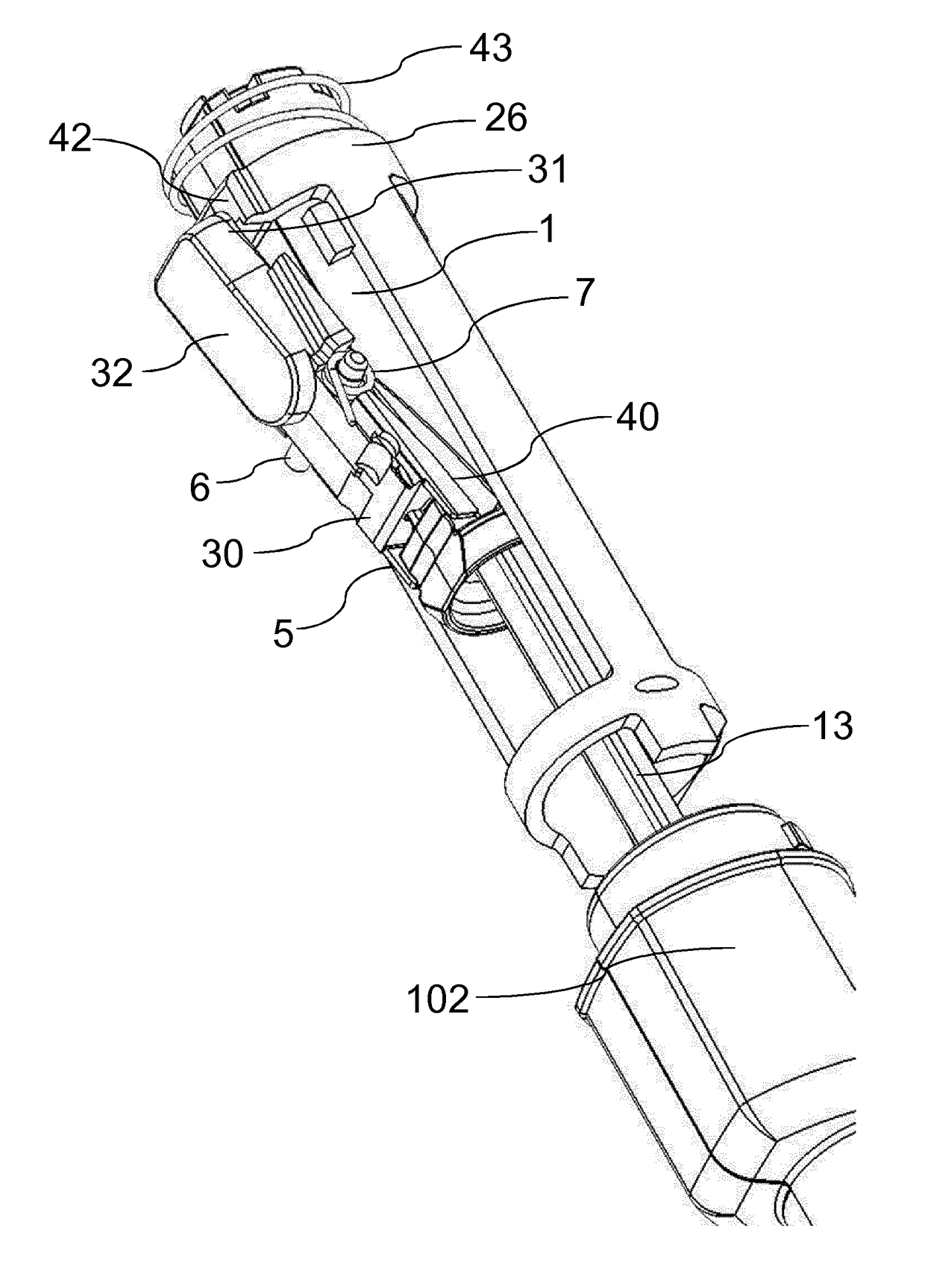
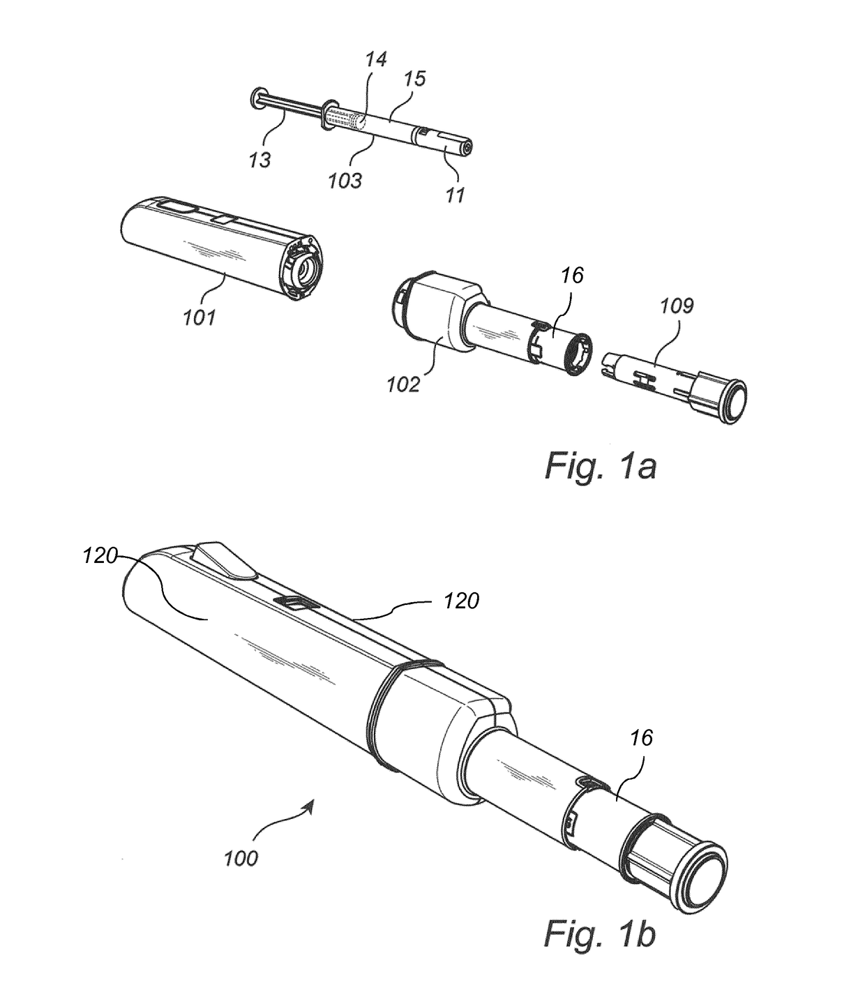
[0030]In one embodiment a reusable auto-injection device 100 according to the invention, as shown in FIGS. 1a and 1b, comprises a rear housing member 101 made from e.g. thermoplastic, a front housing member 102 and a replaceable container subassembly 103, such as a syringe. The rear housing member 101 can be made up of two halves of outer housing 120 which are secured to each other by means of pins or projections provided at one of the halves and corresponding openings in the other half. Obviously, other solutions are imaginable, such as tongue a...


PUM


Abstract

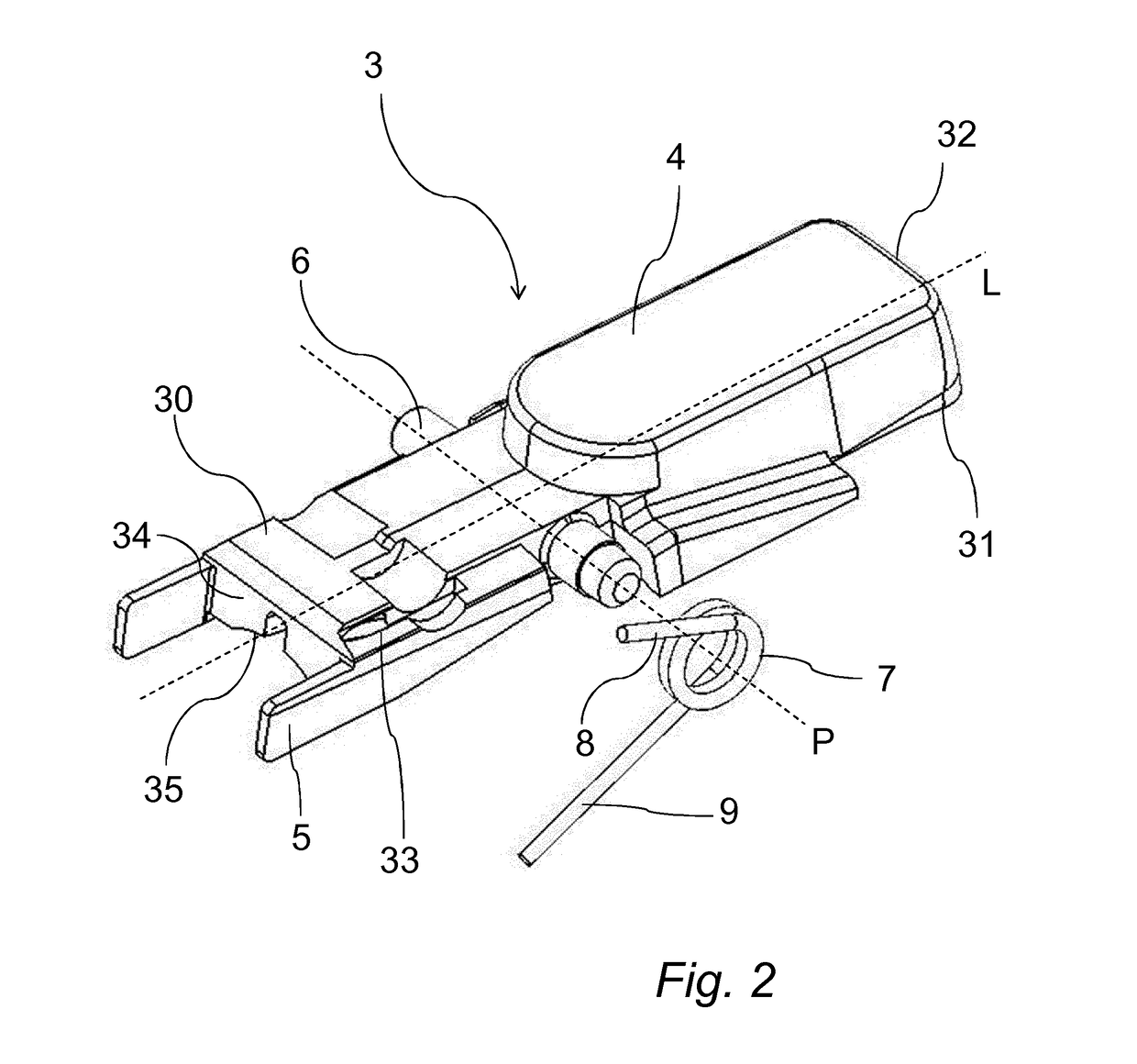
A resettable and reusable auto-injector with a trigger having a pivot axis dividing an elongate body into distal and proximal portions. The proximal portion has a finger surface on an upper section and a bearing surface projecting downwardly configured to engage a button blocker to function as a safety feature to prevent premature firing of the auto-injector before a needle hider is pressed against an injection site.

Description

FIELD OF THE DISCLOSURE[0001]The present invention relates to a trigger mechanism for an auto-injector, specifically to a resettable trigger mechanism for a reusable and resettable auto-injector device.BACKGROUND[0002]Reusable auto injectors that can be loaded with a container subassembly, such as a syringe, are known in the prior art. For example, U.S. Pat. No. 5,599,309 discloses an auto injector for use with proprietary syringes comprising a drive member that receives the rear end of a plunger of a syringe and a trigger for releasing the drive member such that a medicament can be injected. Drawbacks with prior known device is that once the trigger is cocked there is no safety mechanism to prevent a user from accidentally pushing the trigger and firing the device before the auto-injector has been placed against an injection site.SUMMARY OF THE INVENTION[0003]It is therefore an object of the invention to provide a resettable trigger and mechanism for a reusable auto-injector that c...

Claims


Application Information

Patent Timeline
IPC IPC(8): A61M5/315A61M5/31A61M5/32A61M5/20A61M5/46
CPCA61M5/31571A61M5/2033A61M5/46A61M5/31576A61M5/31501A61M5/3202A61M2005/2407A61M5/3245A61M5/3137A61M2005/202A61M2005/206A61M2005/208A61M5/3204
Inventor HOGDAHL, STEFAN
Owner SHL MEDICAL AG
Learn More