Double row tapered rolier bearing apparatus

Inactive Publication Date: 2005-02-08
KOYO SEIKO CO LTD
View PDF9 Cites 18 Cited by
  • Summary
  • Abstract
  • Description
  • Claims
  • Application Information

AI Technical Summary

Benefits of technology

In the double row tapered roller bearing having a structure according to the invention, the intermediate part is formed between the outer ring tracks, and the intermediate part is provided with the relief portion for preventing the mouth of the lubricating hole on the inner periphery of the outer ring from i

Problems solved by technology

As the results, there has arisen such a problem that a surface of the outer ring track 50a may be damaged and life of the bearing may be decreased.
Although there has been an idea of conducting a step for removing the

Method used


Image

  • Double row tapered rolier bearing apparatus
  • Double row tapered rolier bearing apparatus
  • Double row tapered rolier bearing apparatus

Examples


first embodiment

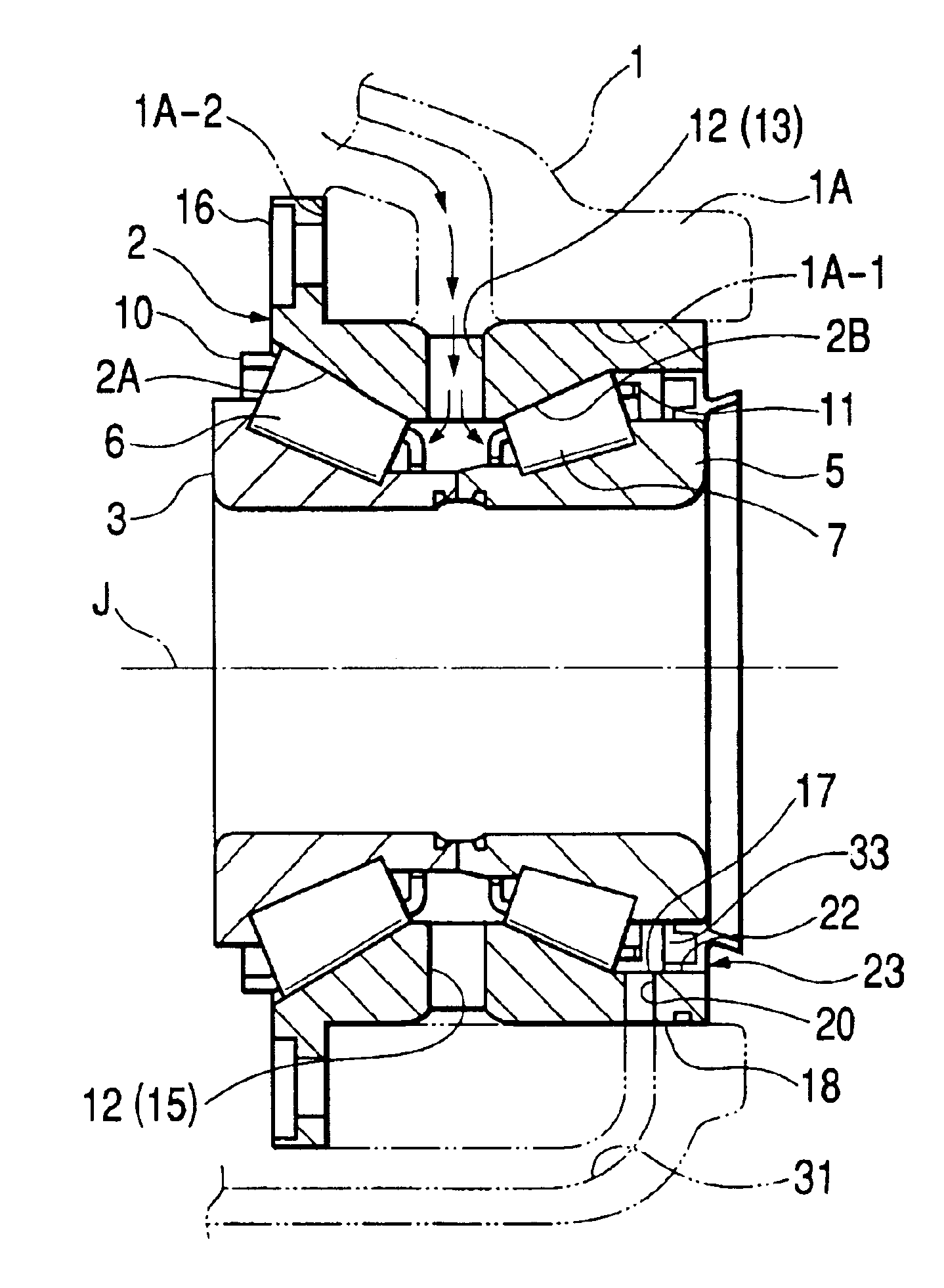
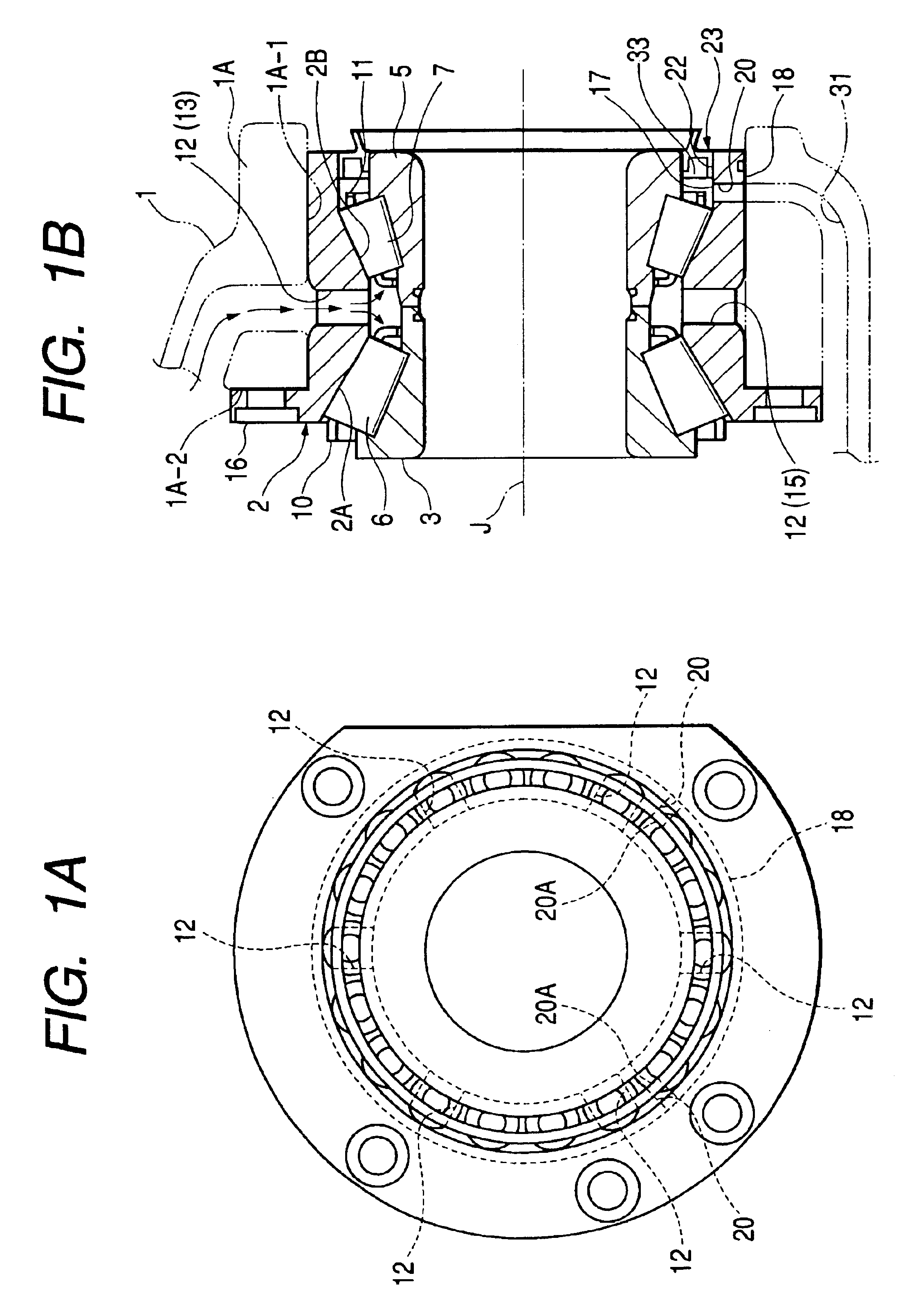
FIG. 1A shows in section a first embodiment of the double row tapered roller bearing apparatus according to this invention. This embodiment includes an integral outer ring 2 which is pressure fitted to an inner peripheral face 1A-1 of an opening 1A in a housing 1, an inward inner ring 3 which is arranged so as to be opposed to an inward track face 2A of the integral outer ring 2, and an outward inner ring 5 which is arranged so as to be opposed to an outward track face 2B of the integral outer ring 2. This embodiment further includes an inward row of conical rollers 6 which is arranged between the inward track face 2A of the integral outer ring 2 and the inward inner ring 3, and an outward row of conical rollers 7 which is arranged between the outward track face 2B of the integral outer ring 2 and the outward inner ring 5. The inward row of the conical rollers 6 is engaged with an annular cage 10, and the outward row of the conical rollers 7 is engaged with an annular cage 11.

The in...

second embodiment

FIG. 3 is a sectional view showing a bevel gear assembly employing the double row tapered roller bearing according to an embodiment of the present invention. In the drawing, a bevel small gear shaft 62 provided with a bevel small gear 62a at its one end (a leftward end in the drawing) is rotatably supported in a housing 61 by a double row tapered roller bearing 70 of this invention. A bevel gear 63 is connected to the bevel small gear 62a so that a power is transmitted between this bevel gear 63 and the bevel small gear shaft 62.

The double row tapered roller bearing 70 includes: a single outer ring 71 having a pair of conical outer ring tracks 71a, 71b on its inner periphery and integrally formed as a whole; a pair of inner rings 72a, 72b which are provided on its outer periphery with conical inner ring tracks 72a1, 72b1 respectively opposed to the outer ring tracks 71a, 71b; a plurality of conical rollers 73a, 73b as rolling bodies which are respectively interposed between the oute...


PUM


Abstract

According to this double row tapered roller bearing apparatus, an integral outer ring (2) is provided with oil vents (20) which extend from an inner peripheral face (17) in an area outward in an axial direction than a rolling face (2B) on which an axially outward row of conical rollers (7) rolls and passes through an outer peripheral face (18). Therefore, a portion of lubricating oil supplied from oil supply holes (13) in the integral outer ring (2) passes the oil vents (20) via the axially outward row of the conical rollers (7), and will be returned to a space in a housing (1) by way of a channel (31) in the housing (1). In conclusion, a circulating path of the lubricating oil through the outward row of the conical rollers (7) can be formed by the oil vents (20).

Description

BACKGROUND OF THE INVENTIONThe present invention relates to a double row tapered roller bearing apparatus which is adapted to support, for example, a pinion shaft constituting a differential gear for a motor vehicle in a cantilever manner so as to freely rotate in a housing.Conventionally, there has been proposed a double row tapered roller bearing apparatus of this type as shown in FIG. 5. This double row tapered roller bearing apparatus includes a double row tapered roller bearing 100 adapted to support a pinion shaft 110 having a pinion 122 which is in mesh with a ring gear, in a cantilever manner with respect to a housing 111. This double row tapered roller bearing 100 includes a row of conical rollers 101 located inwardly in an axial direction, and a row of conical rollers 102 located outwardly in an axial direction. The row of the conical rollers 101 is arranged between a first inner ring 103 and a first track face of an integral outer ring 105, while the row of the conical ro...

Claims


Application Information

Patent Timeline
IPC IPC(8): F16C19/56F16C33/66F16C19/38F16C19/22F16C19/00
CPCF16C19/386F16C19/505F16C33/6651F16C33/6659F16H48/06F16C33/6685F16C2361/61F16H57/0471F16H2048/405F16H2048/423
Inventor YOKOTA, KUNIHIKOKOUDA, KANICHI
Owner KOYO SEIKO CO LTD
Why Eureka
Try Eureka