Intravascular Treatment Site Access

a technology for treating site and intravascular veins, applied in the field of intravascular treatment site access, can solve the problems of difficult access to the target area and delivery of treatment devices, and achieve the effect of minimizing the gap

Active Publication Date: 2017-08-10
MICROVENTION INC
View PDF5 Cites 238 Cited by
  • Summary
  • Abstract
  • Description
  • Claims
  • Application Information

AI Technical Summary

Benefits of technology

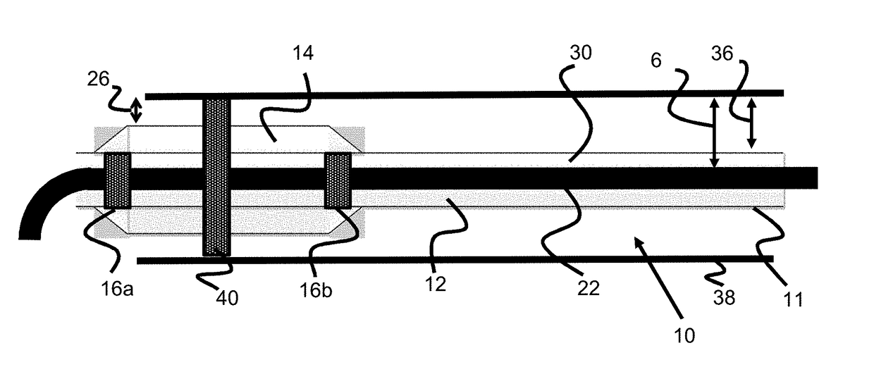
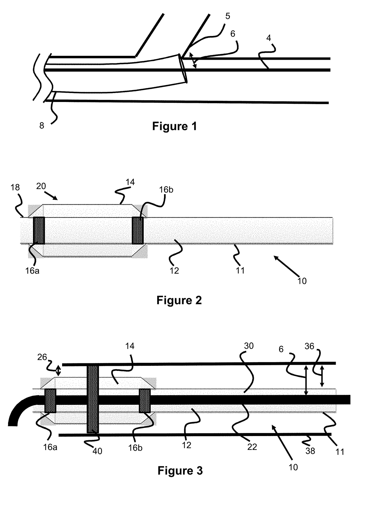
[0005]In one embodiment, a microcatheter with an enlarged distal section is described. The enlarged portion of the microcatheter is located close to the inner diameter of the guide catheter in order to reduce any open space between the microcatheter and the guide catheter, and the guidewire can be placed through the microcatheter and used to guide the system. The microcatheter can include one or more marker bands to aid in aligning the microcatheter correctly relative to the guide catheter. After the guide catheter and microcatheter are tracked to the appropriate treatment site, the microcatheter can then be used to deploy various medical devices to treat a patient.
[0006]In one embodiment, a microcatheter with an enlarged distal section includes multiple marker bands to aid in visualization. The marker bands can be used to align the microcatheter appropriately relative to the guide catheter so that the microcatheter enlarged distal section coincides with the guide catheter distal tip. The guidewire is used to access a treatment site and the microcatheter and guide catheter can be tracked over the guidewire.
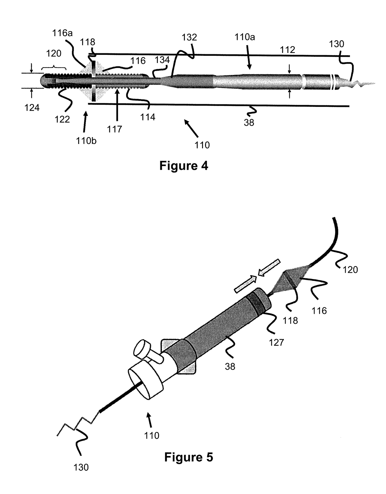
[0008]In one embodiment, a guidewire is described. The guidewire includes a projection to minimize or eliminate the gap between the guidewire and the guide catheter. In one embodiment, the projection is bulbous. The projection can further include a radiopaque marker to aid in imaging and placement of the guidewire.
[0009]In one embodiment, the guidewire includes a shapeable or malleable distal tip and a torque device. The shapeable or malleable distal tip can be bent in a particular direction, and the torque device clamps down on the guidewire to keep it fixed. The guidewire can then be rotated in a particular direction so that the distal tip lines up with a particular blood vessel in order to aid in tracking the guidewire through the vasculature.
[0011]In one embodiment, a rapid exchange system is described. The rapid exchange system minimizes the gap between the guidewire and the guide catheter in scenarios where the catheter can be caught at vessel bifurcations, the rapid exchange system would track over the guidewire and includes a distal enlarged section to bridge the gap between the guidewire and the guide catheter.

Problems solved by technology

The vasculature can be particularly winding or tortuous, especially in the neurovasculature where small, tortuous blood vessels abound, making accessing the target area and delivering treatment devices particularly difficult.

Method used


Image

  • Intravascular Treatment Site Access
  • Intravascular Treatment Site Access
  • Intravascular Treatment Site Access

Examples


Embodiment Construction

[0021]Specific embodiments of the invention will now be described with reference to the accompanying drawings. This invention may, however, be embodied in many different forms and should not be construed as limited to the embodiments set forth herein; rather, these embodiments are provided so that this disclosure will be thorough and complete, and will fully convey the scope of the invention to those skilled in the art. The terminology used in the detailed description of the embodiments illustrated in the accompanying drawings is not intended to be limiting of the invention. In the drawings, like numbers refer to like elements.

[0022]Many interventional procedures utilize a guide catheter, also known as a distal-access catheter (DAC), to access the vicinity of a treatment site. A thin, flexible guidewire is tracked through the vasculature and the guide catheter / DAC is tracked over this guidewire to access the treatment site. Once the region is accessed, a microcatheter is placed thro...


PUM

PropertyMeasurementUnit
lengthaaaaaaaaaa
lengthaaaaaaaaaa
diameteraaaaaaaaaa

Abstract

The embodiments presented herein relate to concepts designed to eliminate the gap between a catheter and guide wire that can otherwise contribute to a catheter getting stuck within the vasculature.

Description

RELATED APPLICATIONS[0001]This application claims priority to U.S. Provisional Application Ser. No. 62 / 293,522 filed Feb. 10, 2016 entitled Intravascular Treatment Site Access, which is hereby incorporated herein by reference in its entirety.BACKGROUND OF THE INVENTION[0002]Guidewires are typically used in interventional procedures to access treatment areas. Guide catheters are typically slid over the guidewire to access the target area and act as a conduit for subsequently deployed microcatheters and / or therapeutic / treatment devices.[0003]The vasculature can be particularly winding or tortuous, especially in the neurovasculature where small, tortuous blood vessels abound, making accessing the target area and delivering treatment devices particularly difficult. In a phenomenon known as the ledge effect, there is a gap between the guidewire and the distal end of the guide catheter which can get caught along blood vessel bifurcations, preventing the catheter from effectively tracking ...

Claims


Application Information

Patent Timeline
Patent Type & Authority Applications(United States)
IPC IPC(8): A61M25/00A61M25/01A61M25/09A61B17/221A61M25/06
CPCA61M25/0041A61B17/221A61M25/0045A61M25/0662A61M25/09016A61M25/09A61M2205/0266A61B2017/22044A61B2017/2215A61M2025/0042A61M2025/0046A61M2025/0183A61M2025/09175A61M25/0108A61B2017/2212A61M25/0023A61M25/09041A61M25/0905A61M2025/0681A61M2025/09116A61M2025/09166A61M25/0068
Inventor TRAN, MICHELLESUMIDA, TETSUGOYAL, MAYANKGULACHENSKI, JOSEPH A.
Owner MICROVENTION INC
Why Eureka
Try Eureka