
Fuel cartridge

a technology of fuel cartridges and fuel cartridges, applied in the direction of fluid pressure control, process and machine control, instruments, etc., can solve the problems of increasing the space available for loading the governors inside the mobile devices, and the effect of increasing the spa

Inactive Publication Date: 2012-05-24
NAKAMURA YASUAKI
View PDF2 Cites 0 Cited by
  • Summary
  • Abstract
  • Description
  • Claims
  • Application Information

AI Technical Summary

Benefits of technology

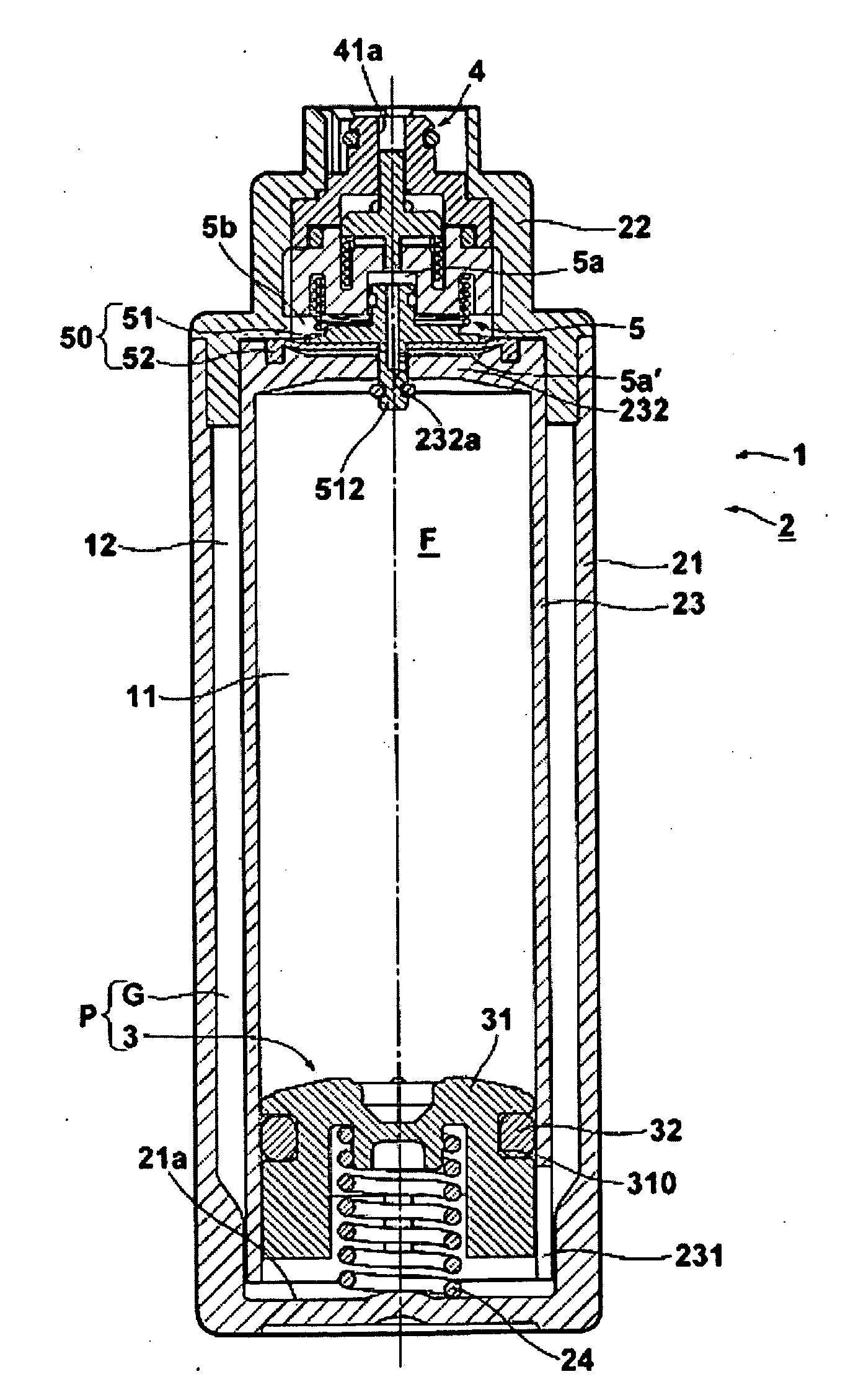
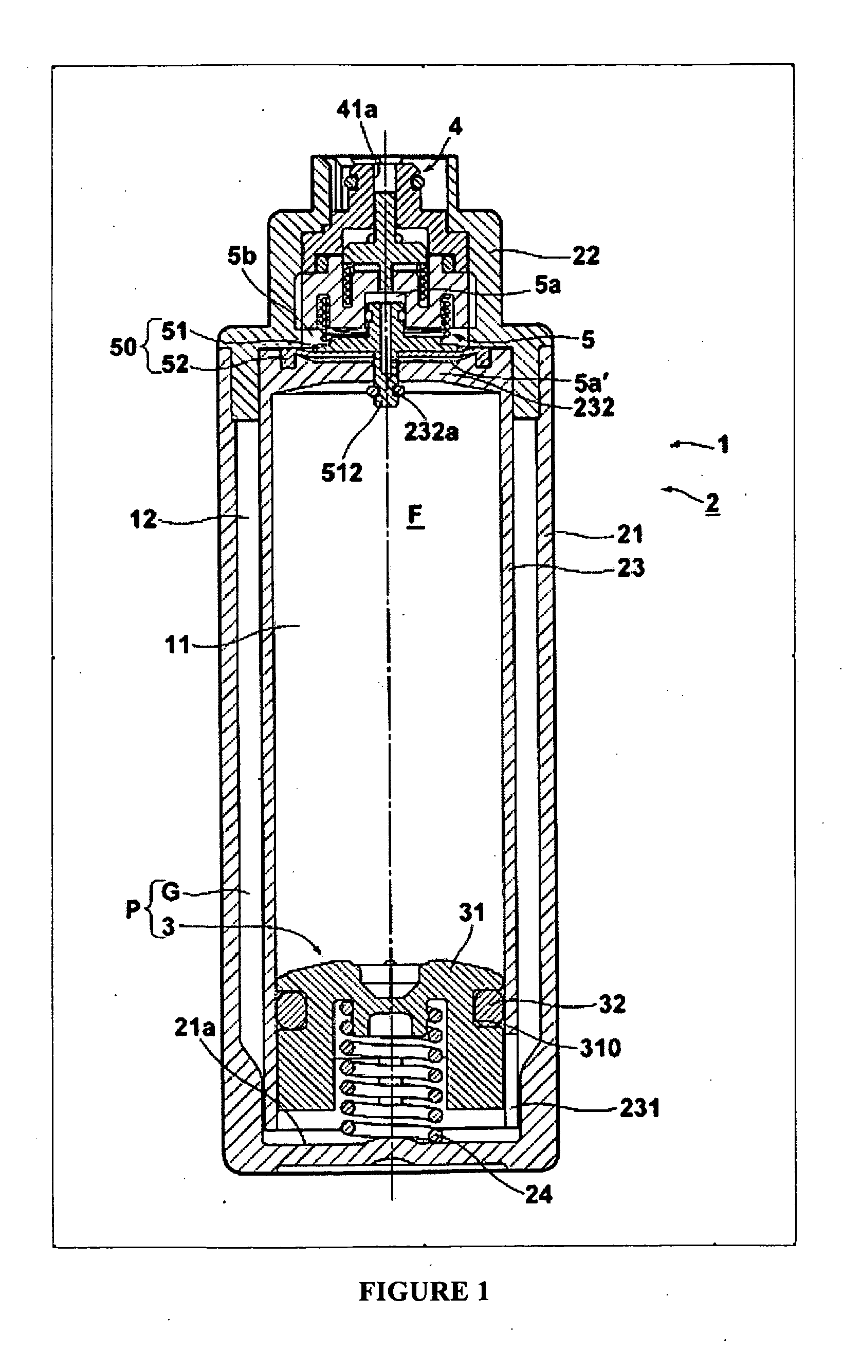
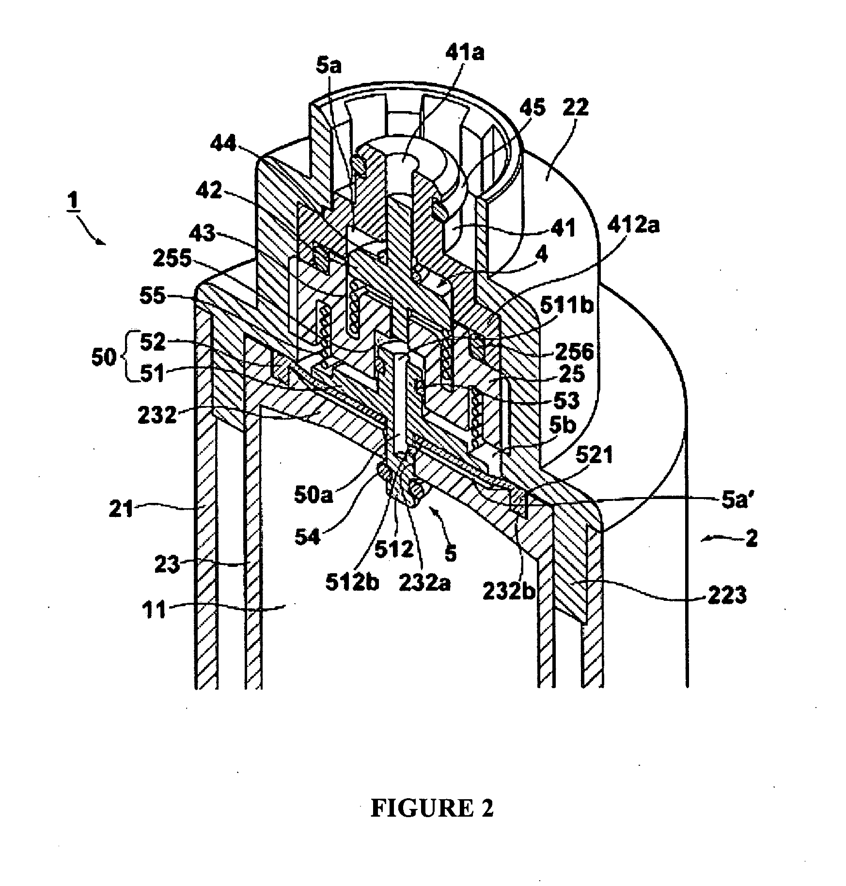
[0024]Since in the inventive fuel cartridge for a fuel cell there is provided a pressure regulating mechanism that causes the fuel that is housed inside the container main body to flow out to a valve, by regulating to a secondary pressure lower than the primary pressure inside the container main body, it can supply fuel to a fuel cell at a fixed flow rate without loading a pressure regulator on the device on the fuel cell is loaded. Owing to this, it is possible to prevent fuel from being supplied abruptly to the fuel cell, and it is moreover possible to miniaturize the space part of the above-mentioned device where the pressure regulating mechanism is loaded. In addition, since the pressure regulating mechanism is provided on the connection part such one end thereof communicates with the valve and the other end thereof communicates with the inside of the container main body, the open space inside the connection part is reduced by just that amount of space in which the pressure regulating mechanism is disposed. Owing to this, it is possible to reduce the fuel that ends up remaining, albeit in minute quantities, inside the connection part, when the connection between the fuel cartridge for a fuel cell and the fuel cell is loosened.Preferred

Problems solved by technology

However, miniaturization of mobile devices like those described above has advanced over the years, and in the future further miniaturization is hoped for, so the space available for loading the governor inside the mobile devices continues to become smaller and smaller.

Method used


Image

  • Fuel cartridge
  • Fuel cartridge
  • Fuel cartridge

Examples


Embodiment Construction

Problems that the Invention Attempts to Solve

[0009]However, in the case of the former fuel container with flexibility, the flow rate is determined by the force of the pressing by the human hand, so when for example the force of the pressing is too strong, the fuel inside the fuel cell is discharged in a rush, and the electrolyte membrane of the fuel cell, which is the place to which the fuel is supplied, is torn by the pressure of the injected fuel.

[0010]In the case of the latter fuel container that utilizes capillary action, the fuel inside the fuel container is supplied slowly at a fixed flow rate, so when the fuel cell requires a large amount of fuel, it ends up taking time for the fuel to be supplied.

[0011]The present invention was created in light of this state of affairs, and takes as its purpose the provision of a fuel cartridge for a fuel cell that supplies fuel to a fuel cell at a fixed flow rate, and that moreover can realize further miniaturization of devices in which fue...


PUM

PropertyMeasurementUnit
volume ratiosaaaaaaaaaa
volume ratioaaaaaaaaaa

Abstract

The existing problem is supplying fuel at a fixed flow rate to a fuel cell, and moreover, miniaturization of the device in which the fuel cell is loaded, in a fuel cartridge for a fuel cell. The fuel cartridge for a fuel cell is equipped with a container main body that is equipped with a connection part that connects to the fuel cell, and houses the fuel that is supplied to the fuel cell in its interior, and a push out means for pushing out the fuel, and a valve that has a supply port for supplying fuel to the fuel cell, and that opens the supply port in response to the operation connecting the container main body to the fuel cell. On the connection part there is provided a pressure regulating mechanism, one end of which communicates with the valve, and the other end of which communicates with the inside of the container main body, and that causes the fuel that is housed in said interior to flow out to the valve, by regulating to a secondary pressure lower than the primary pressure inside the container main body.

Description

BACKGROUND OF THE INVENTION[0001]1. Field of the Invention[0002]The present invention relates to a fuel cartridge for a fuel cell, and relates in particular to a fuel cartridge that is equipped with a pressure regulating mechanism.[0003]2. Description of the Related Art[0004]A fuel cell is an energy conversion apparatus that causes a chemical reaction between hydrogen and oxygen, and generates electricity, owing to the fact that the electrolyte membrane that separates a fuel such as hydrogen, methanol, etc. and oxygen permits hydrogen ions to pass through it, and given the fact that the operating temperature is low, and miniaturization of the apparatus can be anticipated, it is currently used for various purposes, and development has been promoted in such fields as the power supply for mobile devices such that the continuous operating time of for example notebook personal computers and portable telephones can be lengthened.[0005]Then, to replenish the fuel in the fuel cell that is u...

Claims


Application Information

Patent Timeline
Patent Type & Authority Applications(United States)
IPC IPC(8): H01M8/04
CPCH01M8/04208Y02E60/50G05D16/0608
Inventor NAKAMURA, YASUAKI
Owner NAKAMURA YASUAKI
Learn More