Vehicular driving control system

Active Publication Date: 2017-08-10
DENSO CORP
View PDF0 Cites 35 Cited by
  • Summary
  • Abstract
  • Description
  • Claims
  • Application Information

AI Technical Summary

Benefits of technology

[0005]An apparatus described in patent literature 1 estimates feeling of a driver when receiving driving assistance and improves a driving technique of the driver by controlling the amount of driving assistance so that driver is assumed to be able to feel pleasant. However, the inventors of the present disclosure found that the configuration according to patent literature 1 may also cause a difference between a driving style resulting from the driving assistance and the driver's ordinary driving style. In this case, the driver or a fellow passenger feels uneasy.
[0006]It is an object of the invention to provide a vehicular driving control system capable of well preventing a user from feeling uneasy despite provision of driving control with automated driving and/or driving assistance.
[0007]In an example of the present disclosure, a vehicular driving control system for performing vehicular driving control with automated driving and/or driving assistance is provided. The vehicular dr

Problems solved by technology

However, the inventors of the present disclosure found that the configuration according to patent literature 1 may also

Method used


Image

  • Vehicular driving control system
  • Vehicular driving control system
  • Vehicular driving control system

Examples


first embodiment

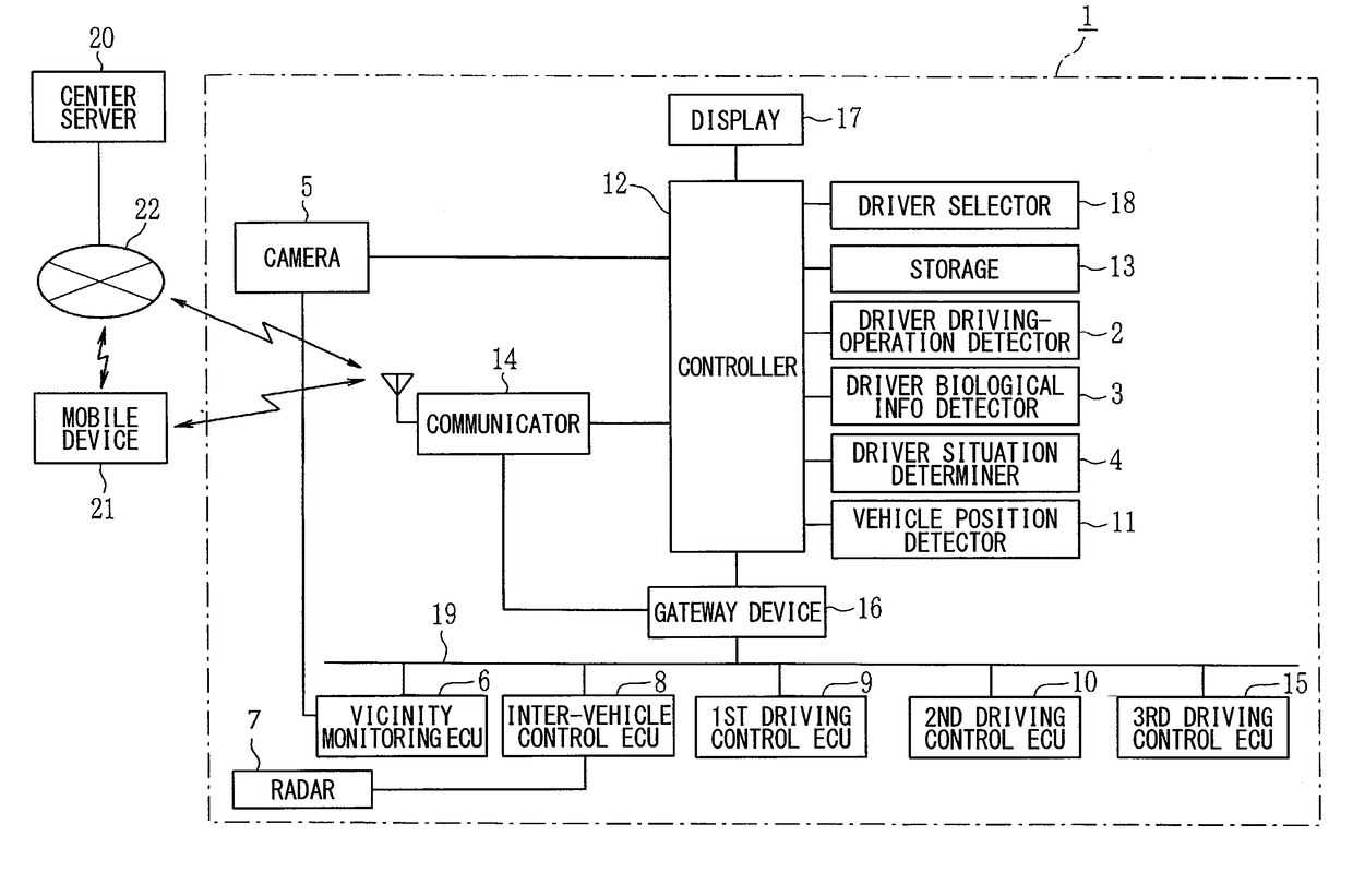
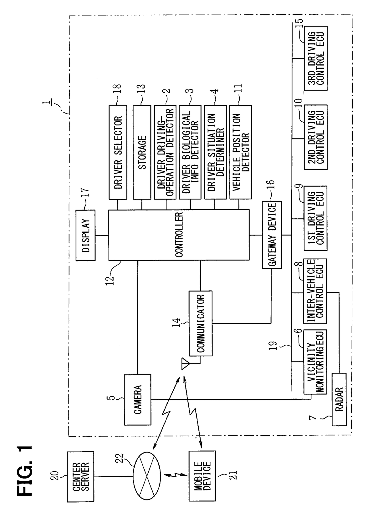
[0045]A first embodiment will be described with reference to FIGS. 1 through 27B. FIG. 1 is a block diagram illustrating a vehicular driving control system according to the embodiment. As illustrated in FIG. 1, a vehicular driving control system 1 includes a driver driving-operation detector 2, a driver biological information detector 3, a driver situation determiner 4, a camera 5, a vicinity monitoring ECU (electronic control unit) 6, a radar 7, an inter-vehicle control ECU 8, a first driving control ECU 9, a second driving control ECU 10, a third driving control ECU 15, a subject vehicle position detector 11, a controller 12, a storage 13, a communicator 14, a gateway device 16, a display apparatus 17, and a driver selector 18.

[0046]The driver driving-operation detector 2 detects driving operation of a driver and outputs a detection signal. Specifically, the driver driving-operation detector 2 detects a speed or accuracy of the driver's driving operation (to manipulate an accelera...

second embodiment

[0201] however, the brain wave sensor 24 measures the user's uneasiness degree when the user gets in the vehicle. The brain wave sensor 24 stores the measurement result as an onboard normal value. The brain wave sensor 24 measures the user's uneasiness degree after the vehicle starts traveling under the condition of no force applied to the user. The brain wave sensor 24 stores the measurement result as a normal value while traveling. While the vehicle is traveling to apply a force (acceleration) to the user, the brain wave sensor 24 measures the user's uneasiness degree for the brain activation region measuring instrument 23 to measure the user's uneasiness degree. The brain wave sensor 24 compares the measurement result with the normal value while traveling. The user is determined to feel uneasy when a difference is greater than or equal to the setup value, namely, the measurement value of the brain wave sensor 24 exceeds shifted threshold value Et2. This configuration determines t...


PUM


Abstract

A vehicular driving control system for performing vehicular driving control based on automated driving and/or driving assistance is provided. The vehicular driving control system includes a driver operation measuring instrument that measures driving operation of a driver, a user uneasiness degree measuring instrument that measures how large a degree of uneasiness of a user is, and a driving control apparatus. When it is determined that the user feels uneasy based on the user uneasiness degree, the driving control apparatus determines an uneasiness factor serving as a source of the uneasiness based on user property data in relation to a traveling situation of a vehicle. Based on the determined uneasiness factor, the driving control apparatus adjusts a control degree of the vehicular driving control, and changes the vehicular driving control so as to decrease the uneasiness of the user.

Description

CROSS REFERENCE TO RELATED APPLICATIONS[0001]This application is based on Japanese Patent Applications No. 2014-179069 filed on Sep. 3, 2014 and No. 2015-140427 filed on Jul. 14, 2015, the disclosures of which are incorporated herein by reference.TECHNICAL FIELD[0002]The present disclosure relates to a vehicular driving control system configured to provide vehicular driving control with automated driving (including driving assistance).BACKGROUND ART[0003]Recently, a vehicle is mounted with an automated driving apparatus or a driving assistance apparatus to perform driving control based on automated driving (including driving assistance). A driving style of the automated driving may differ from a user's ordinary manual operation-based driving style if the user (driver or fellow passenger) is not accustomed to the driving style of the automated driving. The driving style of the manual operation differs from user to user and reflects the driver's habit (individuality) because the manua...

Claims


Application Information

Patent Timeline
IPC IPC(8): B60W30/02B60W30/08A61B5/0476
CPCB60W30/025A61B5/0476B60W30/08B60W50/10B60W2050/0071B60W50/0098B60W2050/0002A61B5/0261A61B5/18A61B5/6803A61B5/6893B60W30/18B60W2050/0075B60W2540/22B60W2540/30B60W2540/043B60W2552/05B60W2556/50A61B5/369
Inventor YOSHIDA, ICHIROSAWADA, KIYOHIKO
Owner DENSO CORP
Why Eureka
Try Eureka