Buoy With Integrated Motion Compensation

a technology of motion compensation and buoys, which is applied in the field of floating buoys, can solve the problems of unsatisfactory aesthetics, unsatisfactory motion compensation, and low noise of turbines, and achieve the effect of mitigating the negative effects of motion

Active Publication Date: 2017-08-10
UNIVERSITY OF MAINE
View PDF1 Cites 18 Cited by
  • Summary
  • Abstract
  • Description
  • Claims
  • Application Information

AI Technical Summary

Problems solved by technology

These large groups of wind turbines can generate undesirably high levels of noise and may be viewed as aesthetically unpleasing.
An optimum flow of air may not be available to these land-base wind turbines due to obstacles such as hills, woods, and buildings.

Method used


Image

  • Buoy With Integrated Motion Compensation
  • Buoy With Integrated Motion Compensation
  • Buoy With Integrated Motion Compensation

Examples


Embodiment Construction

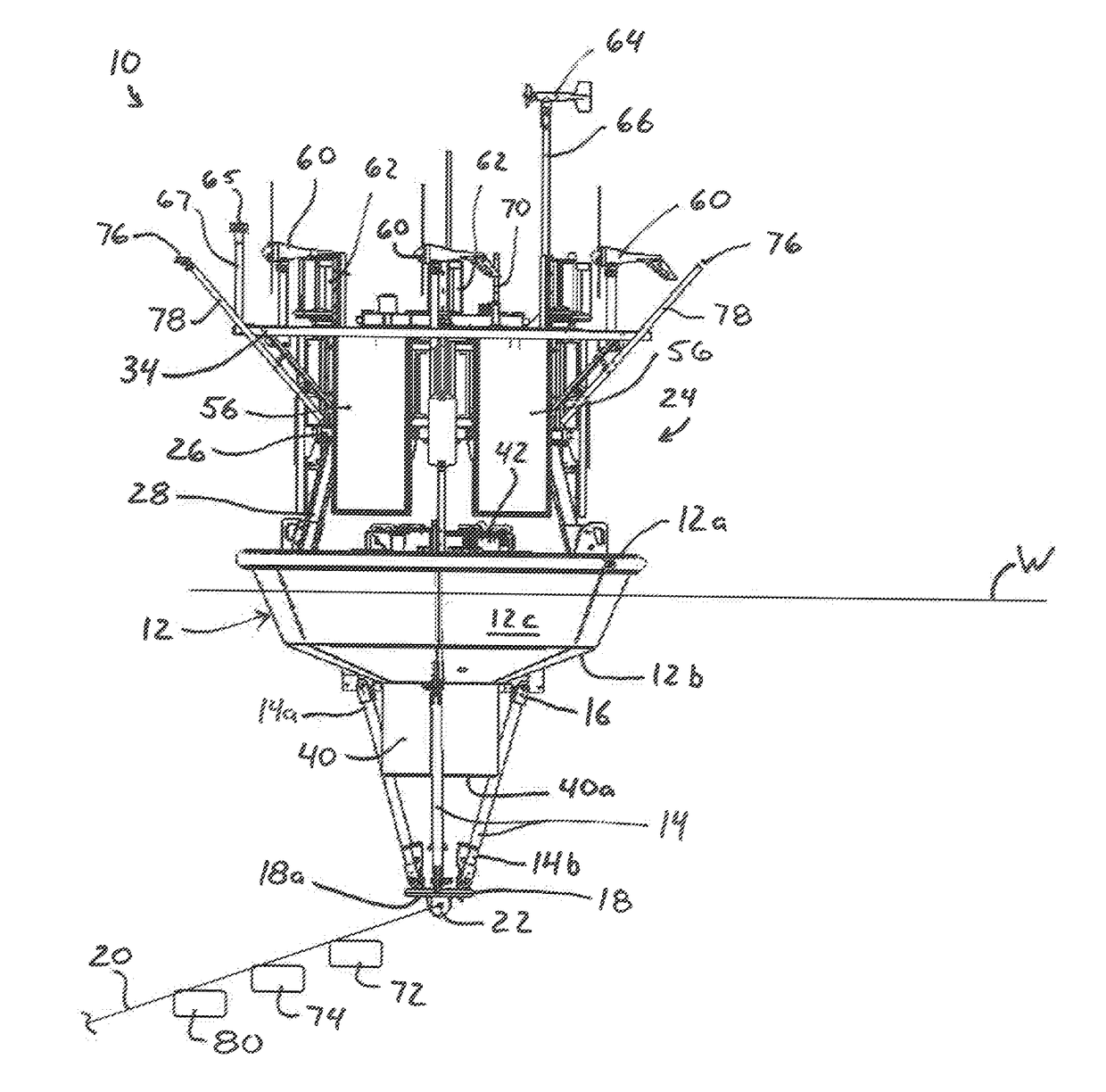
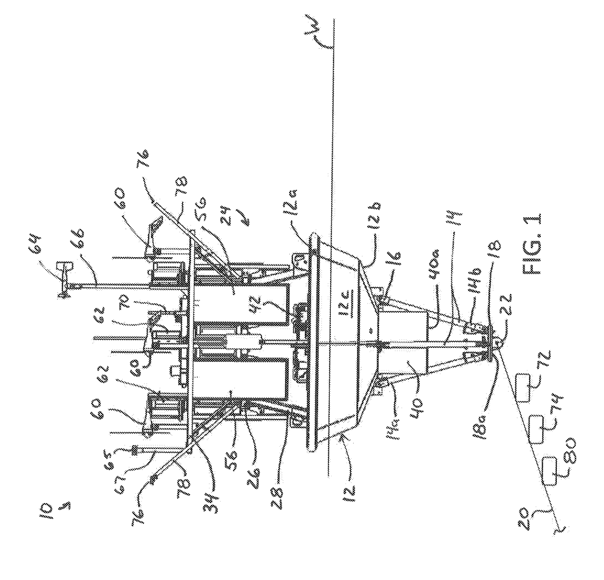
[0018]Referring now to the drawings, there is illustrated in FIG. 1 a buoy 10 that includes a plurality of sensors in accordance with the present invention. The embodiments of the invention disclosed below generally provide improvements to a floating buoy that housing the sensors required to evaluate wind farm site locations at hub heights of about 100 m and higher, design wind turbines, and operate and maintain wind turbines. The improved floating buoy 10 also includes means to mitigate the negative effects of motion caused by waves on remote wind sensing equipment such as a Light Detection and Ranging (LiDAR) wind speed measurement sensor 82, described in detail below, mounted on the buoy 10. The improved floating buoy 10 may be configured to provide the data collected by the sensors to a computer server on-shore, an offshore monitoring station, or to one or more fixed or floating off shore wind turbine platforms.

[0019]The illustrated buoy 10 is a wave rider type buoy configured t...


PUM


Abstract

A floating buoy includes a buoy hull having a tower that extends outwardly from the hull. A plurality of sensors are mounted either on the buoy hull, within the buoy hull, and / or on the tower. The plurality of sensors includes at least one met-ocean sensor, at least one ecological sensor, and at least one wind speed measurement sensor. The floating buoy further includes an autonomous power system that is configured to provide electrical power to each of the plurality of sensors. The wind speed measurement sensor may be a Light Detection and Ranging (LiDAR) wind speed measurement sensor, a surface level wind speed sensor, an ultrasonic wind speed sensor, or SODAR.

Description

CROSS REFERENCE TO RELATED APPLICATIONS[0001]This application claims the benefit of U.S. Provisional Application No. 62 / 036,342, filed Aug. 12, 2014.BACKGROUND[0002]This invention relates in general to floating buoys having a variety of data collection devices collecting data that is useful for offshore wind turbines. In particular, this invention relates to an improved structure for a floating buoy that includes one or more of the sensors required to evaluate wind farm site locations, generate meteorological and met-ocean data useful for the design wind turbines, and operate and maintain offshore wind turbines, and further includes means to mitigate the negative effects of motion caused by waves on remote wind sensing equipment that is capable of measuring wind speed at wind turbine hub heights of about 100 m and higher, such as LiDAR wind speed measurement equipment or SODAR.[0003]Wind turbines for converting wind energy to electrical power are known and provide an alternative ene...

Claims


Application Information

Patent Timeline
Patent Type & Authority Applications(United States)
IPC IPC(8): B63B22/20G01P5/00G01S17/58B63B22/04
CPCB63B22/20B63B22/04B63B2022/006G01S17/58G01P5/00B63B22/18B63B2035/446B63B2209/18B63B2211/02
Inventor DAGHER, HABIB J.PETTIGREW, NEALVISELLI, ANTHONY M.JOYCE, RACHAELWALLINGA, JOHNFIKES, PATRICKFISHER, NEAL
Owner UNIVERSITY OF MAINE
Why Eureka
Try Eureka