Foldable tubular element with one rigid degree of freedom

a tubular element and rigid degree technology, applied in the field of folding tubular elements, can solve the problems of imposing limitations on the application of the element, the difficulty in accurately controlling etc., and achieve the effects of reducing the complexity of the folding and expanding process, facilitating storage and transportation, and convenient assembly

Active Publication Date: 2017-08-10
TIANJIN UNIV
View PDF1 Cites 0 Cited by
  • Summary
  • Abstract
  • Description
  • Claims
  • Application Information

AI Technical Summary

Benefits of technology

[0004]The object of the invention is to overcome drawbacks of the prior art and also provide a foldable tubular element with one rigid degree of freedom capable of accurately controlling folding and expanding process of the element, reducing complexity of folding and expanding the element, and being capable of repeated used.
[0008]The foldable tubular element of the invention is constructed of planar units to which no deformation will occur and a rotation pair formed by connection lines of two adjacent planar units. Accurate control may be done to the folding and expanding process of the element. Furthermore, as the tubular element of the invention only has one rigid degree of freedom, complexity in folding and expanding of the element is further reduced. Therefore, the present element is more reliable than a prior art element and may be reused.
[0009]The tubular element of the invention may be designed using a simple method and, may be assembled conveniently. As the entire element can be folded into a compact arrangement, storage and transportation of the same is also facilitated. In addition, the tubular element of the invention is not intended to be limited to one with specific shape or size. It may also meet different requirements with different purposes.

Problems solved by technology

It is hard to accurately control the process of folding and expanding and this imposes limitation on their application.

Method used


Image

  • Foldable tubular element with one rigid degree of freedom
  • Foldable tubular element with one rigid degree of freedom
  • Foldable tubular element with one rigid degree of freedom

Examples


Embodiment Construction

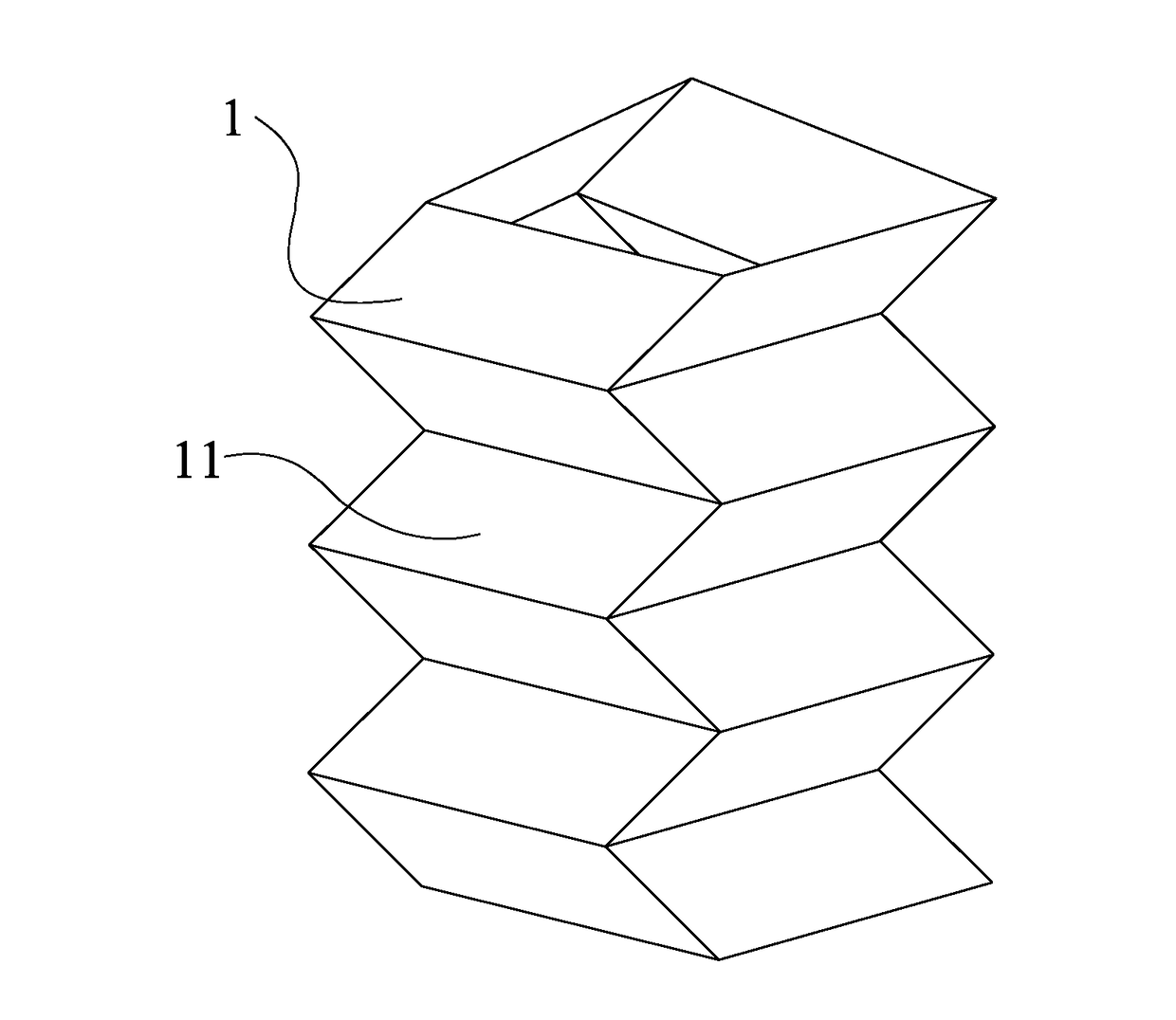
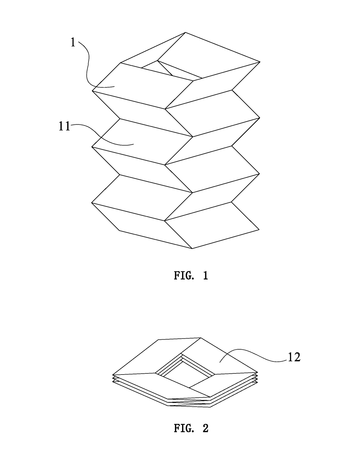
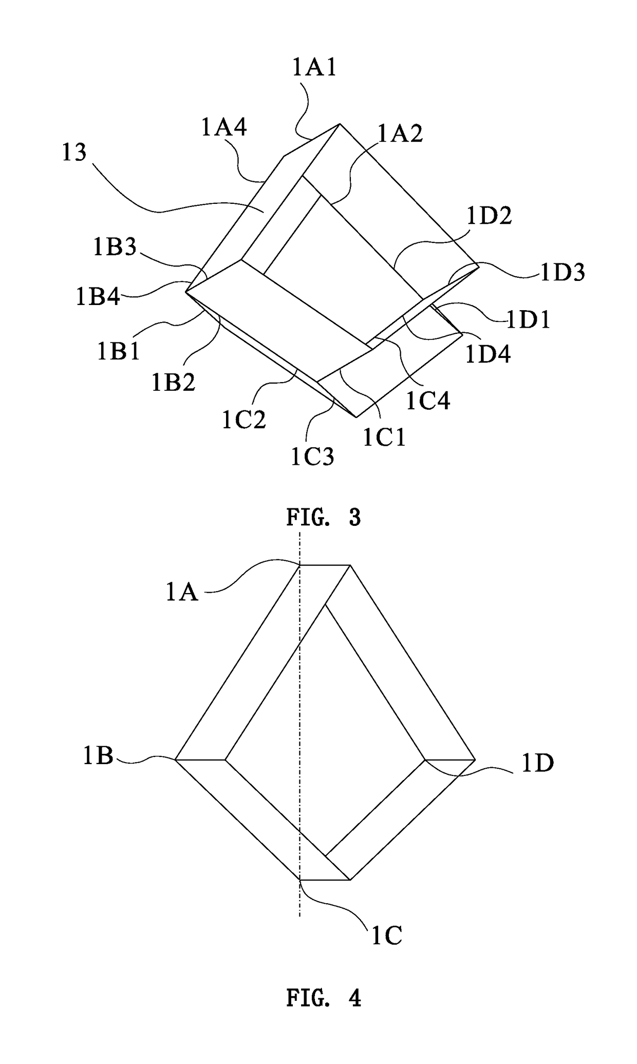
[0093]The present invention will be described below in conjunction with drawings and embodiments.

[0094]A foldable tubular element with one rigid degree of freedom according to the invention is of a tubular construction formed by a number of single layered annular units which are connected in sequence. Each single layered annular unit is of a prism having N sides. Two adjacent prisms each having N sides are connected to each other by sharing a polygon with N sides formed on an intersection plane defined by connection of a first and a final ridge lines. Each prism with N sides is composed of N rigid planar quadrilateral facets. Two adjacent single layered annular units comprise N spherical mechanisms formed by intersection of only four planar quadrilateral facets around an apex. The polygon having N sides formed in the intersection plane of the two adjacent single layered annular units is a planar polygon with arbitrary sides in addition to triangle. When N is an even number, and the ...


PUM


Abstract

A foldable tubular construct / element with one rigid degree of freedom is of a tubular construction formed by a number of single layered annular units which are connected in sequence; each single layered annular unit is of a prism having N ridge lines; two adjacent prisms each having N sides are connected to each other by sharing a polygon with N sides formed on an intersection plane; each prism with N ridge lines is composed of N rigid planar quadrilateral facets; two adjacent single layered annular units comprise N spherical mechanisms formed by the intersections of only four planar quadrilateral facets at each apex; the polygon having N sides formed in the intersection plane of the two adjacent single layered annular units is a planar polygon with an arbitrary number of sides greater than for a triangle; the ridge lines of each prism having N ridge lines are parallel to each other; the connecting ridge lines of the tubular element are coplanar; when the polygon having N sides formed in the intersection plane of the two adjacent single layered annular units is a line-symmetric polygon of even number of sides with at least one diagonal symmetric axis, the plane in which connecting ridge lines of the tubular element are located is perpendicular to one diagonally symmetric axis.

Description

CROSS-REFERENCE TO RELATED APPLICATIONS[0001]This is a CIP application based on PCT Application No. PCT / CN2013 / 075521, filed May 11, 2013, which claims priority from CN Application No. 201210528507.5, filed Dec. 5, 2012. The contents of the prior applications are incorporated herein in the entirety by reference.FIELD OF THE INVENTION[0002]The present invention relates to a foldable construction and more particularly, relates to a foldable tubular element with one rigid degree of freedom.BACKGROUND OF THE INVENTION[0003]An expandable and foldable tubular element composed of a number of planar units has various uses. For example, it may be used as a huge construction of space station, construction of moon base, used as support for human body blood vessel or digestive tract, or used as large or intermediate temporary residences after occurrence of serious natural disaster. When expanded, this kind of tubular element will define a space with certain volume. Also, it can be reduced to it...

Claims


Application Information

Patent Timeline
Patent Type & Authority Applications(United States)
IPC IPC(8): E04B1/343A61F2/844E04H15/32E04C2/40E04C2/42
CPCE04B1/34357E04C2/40A61F2/844E04H15/32E04C2/427Y10T428/24686Y10S52/10B64G99/00E04B1/3449A01G9/00A63H33/16E04B1/32E04B1/343E04B7/10E04B7/107E04B2001/3247E04B2001/327E04B2001/3294E04C2/30E04C2/42E04H15/52H05K999/99
Inventor CHEN, YANLIU, SICONGLI, JIANMINWANG, KUNFENGLV, WEILINSHIGETOMI, KAORI
Owner TIANJIN UNIV
Why Eureka
Try Eureka