Hybridisation of the compressors of a turbojet

a turbojet and compressor technology, applied in the field of aeronautical turbine engines, can solve the problems of mechanical damage, extinction of combustion chambers, etc., and achieve the effects of reducing constraints on turbine engine designers, improving the operation of turbojet engines, and optimizing the surge margin of compressors

Pending Publication Date: 2017-08-10
SN DETUDE & DE CONSTR DE MOTEURS DAVIATION S N E C M A
View PDF8 Cites 63 Cited by
  • Summary
  • Abstract
  • Description
  • Claims
  • Application Information

AI Technical Summary

Benefits of technology

[0005]The aim of the present invention is to overcome these drawbacks by proposing a device for optimising the surge margin of the compressor so as to reduce the constraints on the designers of turbine engines. Another aim of the present invention is to improve the operation of the turbojet engine in the in-flight idle phase.

Problems solved by technology

This phenomenon, which results from an excessive incidence of the airflow on the blades of one of the compressors, results in large and rapid fluctuations in the pressure downstream of the compressor in question and may lead to extinction of the combustion chamber.
It also generates strong jolts on the bladings of the compressor and may thus lead to mechanical damage.

Method used


Image

  • Hybridisation of the compressors of a turbojet
  • Hybridisation of the compressors of a turbojet
  • Hybridisation of the compressors of a turbojet

Examples


Embodiment Construction

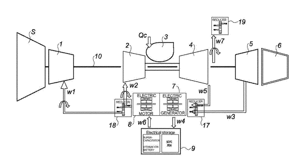
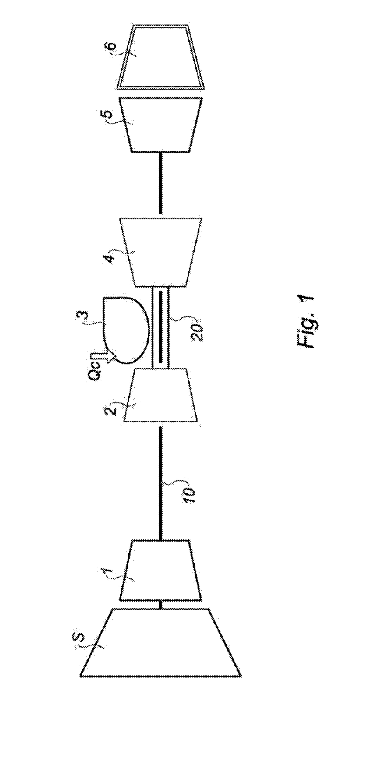
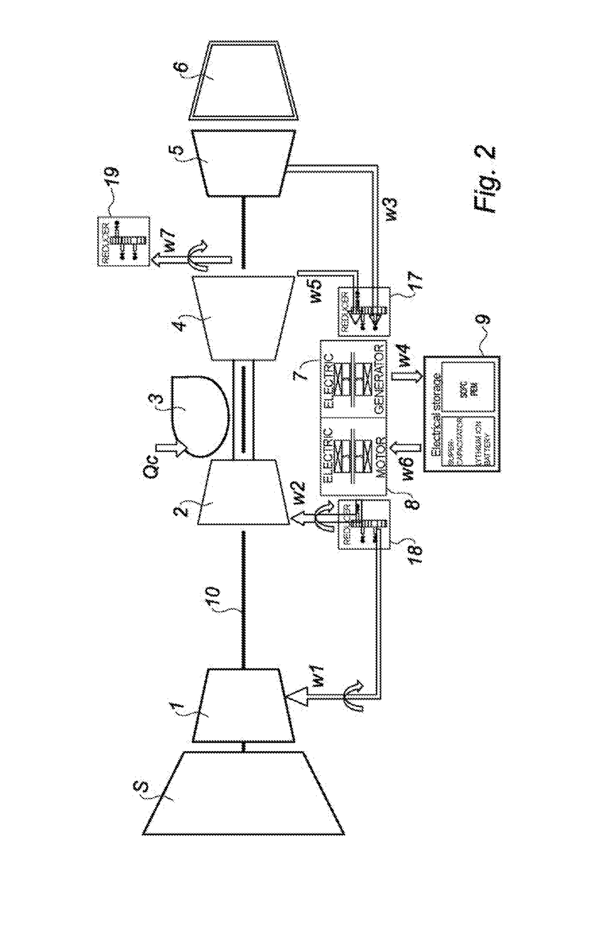
[0029]FIG. 1 is a generic view of a fan twin-spool bypass turbojet engine. It comprises conventionally, from upstream to downstream in the direction of flow of the gases, a fan S, a low-pressure compressor 1, a high-pressure compressor 2, a combustion chamber 3 that receives a flow of fuel Qc, a high-pressure turbine 4, a low-pressure turbine 5 and a primary exhaust pipe 6. The low-pressure (or LP) compressor 1 and the low-pressure turbine 5 are connected by a low-pressure shaft 10 and together form a low-pressure body. The high-pressure (or HP) compressor 2 and the high-pressure turbine 4 are connected by a high-pressure shaft 20 and together form, with the combustion chamber, a high-pressure body.

[0030]The fan S, which is driven, either directly or by means of a reducer, by the LP shaft 10, compresses the air coming from the air inlet sleeve. This air is divided, downstream of the fan, between a secondary airflow that is directed directly to a secondary nozzle (not shown), through...


PUM


Abstract

twin-flow, double body turbojet includes a fan that is positioned upstream from a gas generator and delimits primary and secondary flows. The gas generator is traversed by the primary flow and includes a low-pressure compressor, a high-pressure compressor, a combustion chamber, a high-pressure turbine and a low-pressure turbine. The low-pressure turbine is linked to the low-pressure compressor by a low-pressure rotating shaft, and the high-pressure turbine is linked to the high-pressure compressor by a high-pressure rotating shaft. The turbojet has an electric motor for injecting mechanical power into at least one of the rotating shafts. The turbojet also has a device for removing power from at least one of the rotating shafts and transforming the excess power into electrical energy. An electric storage means is positioned between the device for removing power and the electric motor.

Description

FIELD OF THE INVENTION[0001]The field of the invention is that of aeronautical turbine engines, and in particular that of aircraft engines produced in the form of twin-spool bypass turbojet engines having a high bypass ratio.PRIOR ART[0002]The design of modern turbojet engines requires taking into account a sufficient margin against the phenomenon known as surge for sizing the compressors thereof. This phenomenon, which results from an excessive incidence of the airflow on the blades of one of the compressors, results in large and rapid fluctuations in the pressure downstream of the compressor in question and may lead to extinction of the combustion chamber. It also generates strong jolts on the bladings of the compressor and may thus lead to mechanical damage. It is therefore particularly necessary to avoid the appearance thereof. The operation of a compressor in use is generally represented by a diagram that expresses the pressure ratio obtained between the outlet and the inlet, a...

Claims


Application Information

Patent Timeline
Patent Type & Authority Applications(United States)
IPC IPC(8): F02C7/32F02K3/06
CPCF02C7/32F02C7/36F02K3/06F05D2220/76Y02T50/60F04D27/0269F04D27/0261F01D15/10F02C3/113F02C7/268
Inventor ROBIC, BERNARDOBRECHT, THIERRY JEAN-JACQUESRENAULT, BAPTISTE JEAN MARIE
Owner SN DETUDE & DE CONSTR DE MOTEURS DAVIATION S N E C M A
Why Eureka
Try Eureka