An optical inspection system

an optical inspection and optical technology, applied in the field of preform optical inspection systems, can solve problems such as gravity feeding, and achieve the effects of convenient maintenance, reduced time, and simplified system geometry

Inactive Publication Date: 2017-08-10
COLTON WILLIAM
View PDF3 Cites 2 Cited by
  • Summary
  • Abstract
  • Description
  • Claims
  • Application Information

AI Technical Summary

Benefits of technology

The patent describes a system for inspecting preforms made by injection molding. The system uses a conveyor to transport the preforms through an optical inspection unit which can detect any faults in the preform. This data is then transferred to a control system which can adjust the process parameters to correct any issues. As a result, the system can make real-time adjustments to improve the quality of the preforms and increase the likelihood of them passing quality inspection. Overall, the system is efficient, cost-effective, and offers a quick and effective way to inspect preforms.

Problems solved by technology

Therefore, they are not gravity fed.

Method used


Image

  • An optical inspection system
  • An optical inspection system
  • An optical inspection system

Examples


Embodiment Construction

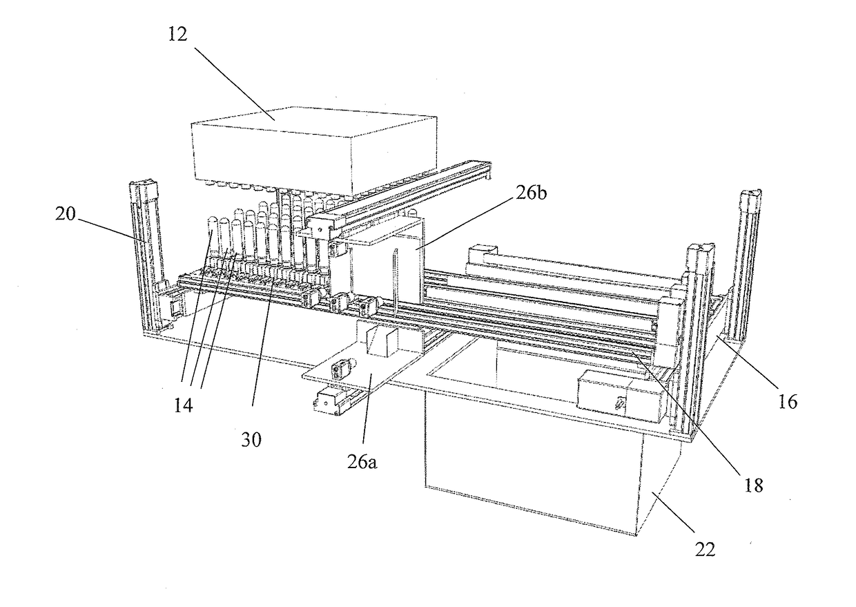
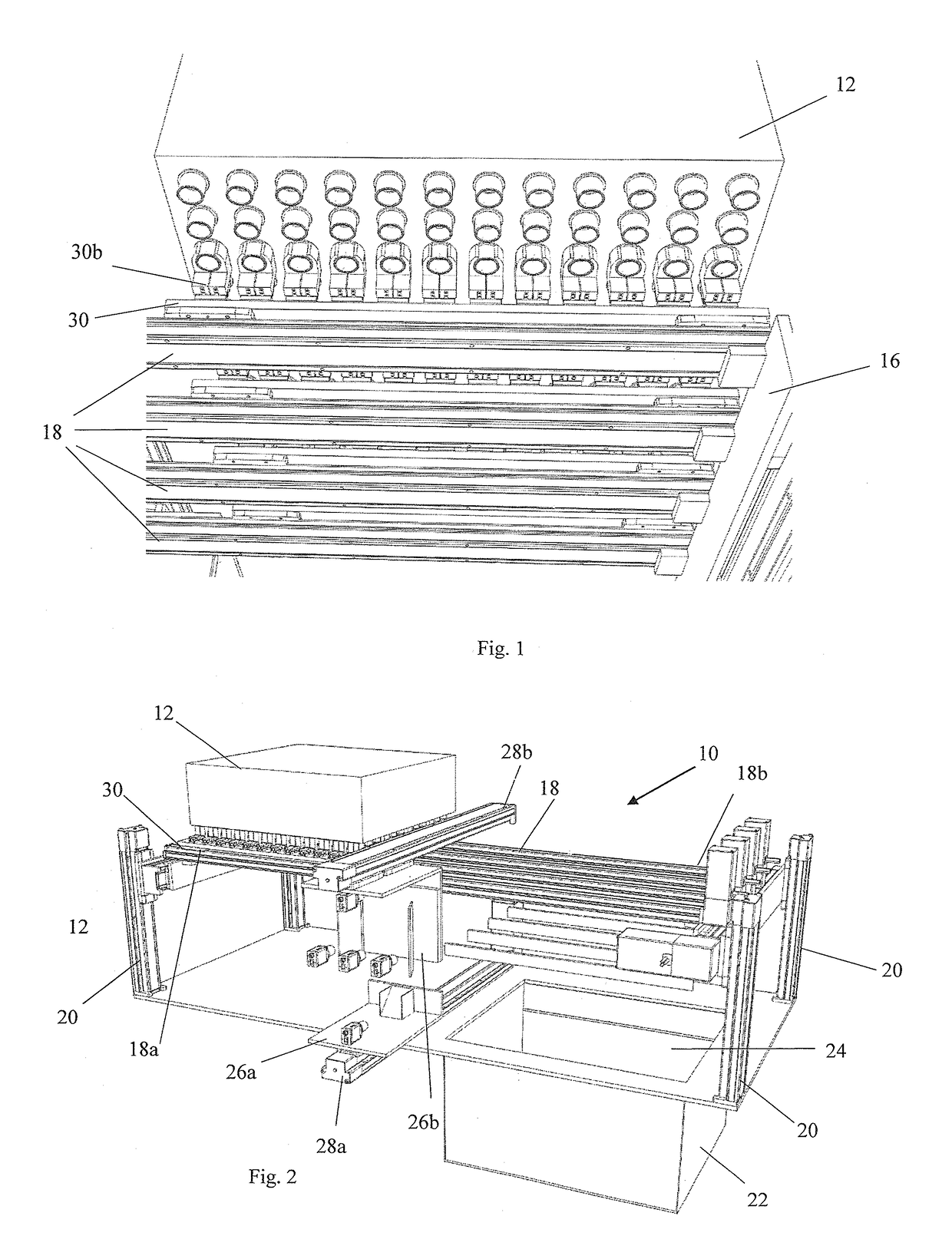
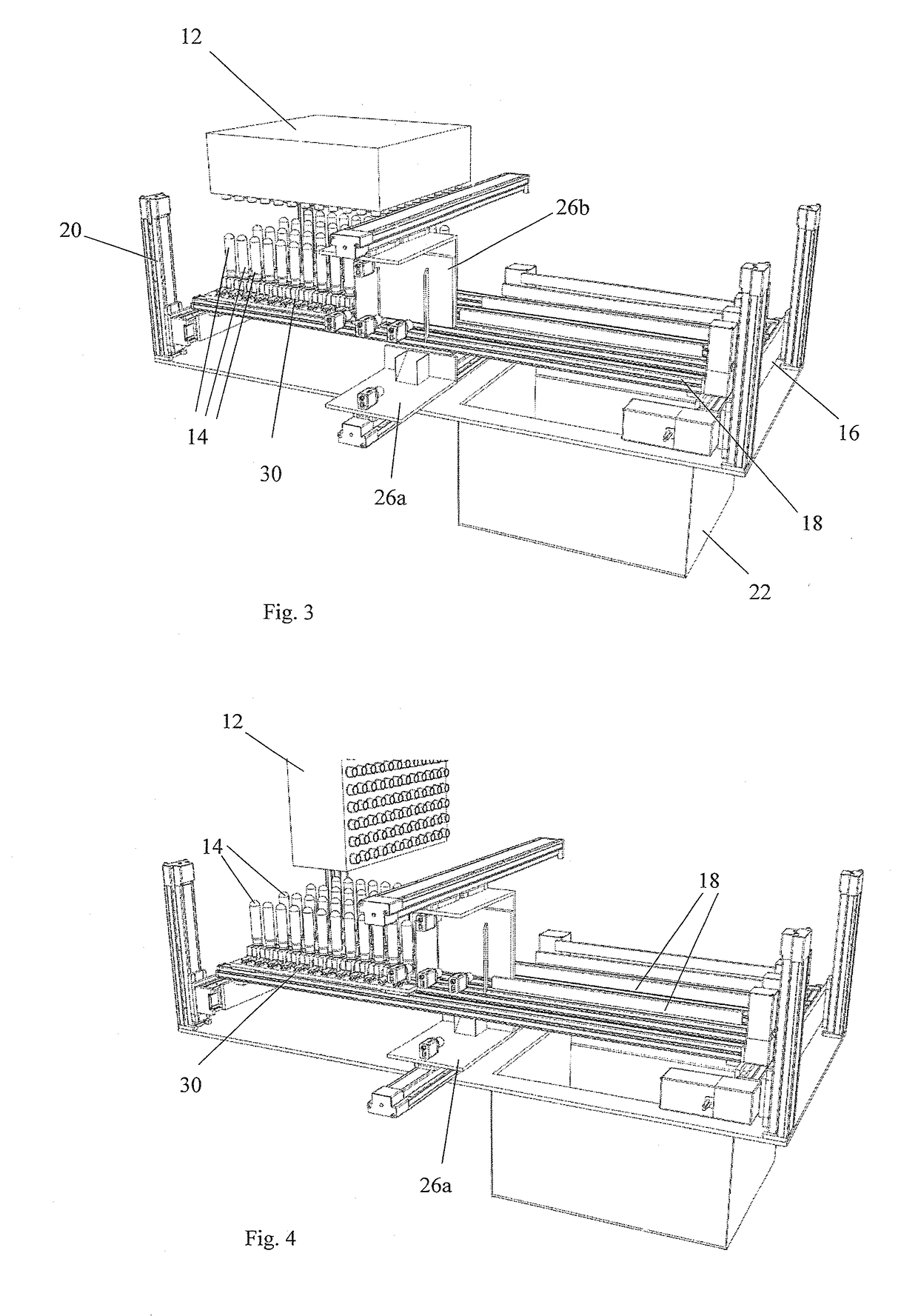
[0050]FIGS. 1 to 17 show a system 10 comprising a tool 12 adapted for receiving preforms 14 from an injection moulding device (not shown). The tool 12 is arranged above a conveyor system 16 that comprises a plurality of lane conveyors 18. The conveyor system 16 has stanchions 20 that allow the conveyor system 16 to be moved vertically up and down, relative to the tool 12. The conveyor system 16 is also able to be moved horizontally in the direction substantially perpendicular to the lane conveyors 18.

[0051]The lane conveyors 18 of the conveyor system 16 are arranged substantially in parallel and comprise a first end 18a positioned underneath the tool 12 and they extend away from the first end 18a to a second end 18b.

[0052]The second end 18b of the lane conveyors is positioned above a distribution conduit 22. The distribution conduit 22 has an open top and within the distribution conduit 22 is a moveable directing partition 24 that has a first position and a second position.

[0053]Al...


PUM

PropertyMeasurementUnit
Lengthaaaaaaaaaa

Abstract

A preform optical inspection system includes a plurality of carrier units, each mounted on a respective lane conveyor for receiving preforms from an injection molding device and an optical inspection unit. The optical inspection unit is able to transverse movement across the lane conveyors and the carrier units are able to pass though the optical inspection unit.

Description

FIELD OF THE INVENTION[0001]The invention relates to a preform optical inspection system and a method of operating the same.BACKGROUND TO THE INVENTION[0002]Injection Mould Machines are commonly used to inject plastic into an array of dies (cavities), forming multiple parts each time the press cycles. Preforms which are later blown into bottles are an example of products which can be produced using such machines. The cycle of the press is usually in the following order, press closes, plastic is injected into each die (cavity) forming the parts, the press then opens leaving a gap between the mould halves where the parts are ejected.[0003]At the point of ejection parts are often removed from the mould by a robot tool which slides between the two halves of the mould receiving the preforms into an array of tubes which matches the exact layout of the mould.[0004]The robot tool maintains the sequence of parts in the same order as in the mould. The parts are also still orientated in the sa...

Claims


Application Information

Patent Timeline
IPC IPC(8): G01N21/90B29C49/06B29C45/76B29C49/78
CPCG01N21/9081B29C49/78B29C2945/76464B29C45/7686G01N2021/8455B29C49/061B29C31/002B29C2037/90B29C2049/023
Inventor COLTON, WILLIAM
Owner COLTON WILLIAM
Why Eureka
Try Eureka