Vehicle brake system

Active Publication Date: 2017-08-17
TOYOTA JIDOSHA KK
View PDF10 Cites 18 Cited by
  • Summary
  • Abstract
  • Description
  • Claims
  • Application Information

AI Technical Summary

Benefits of technology

[0006]The hydraulic brake device has the advantage of high reliability, and the electric brake device has the advantage of good response.

Problems solved by technology

These brake devices, however, have respective drawbacks.
Here, “one of the hydraulic braking force and the electric braking force decreases” means that the one of the braking forces is smaller than the braking force that should be generated, namely, the one of the braking forces is insufficient.
Further, the situation may be a situation in which the one of the hydraulic braking force and the electric braking force becomes smaller than expected in the process of increase of the one of the braking forces due to a delay in response with respect to the increase.
In this case, the response of the hydraulic braking f

Method used


Image

  • Vehicle brake system
  • Vehicle brake system
  • Vehicle brake system

Examples


embodiment 1

A. Outline of Vehicle Drive System and Vehicle Brake System

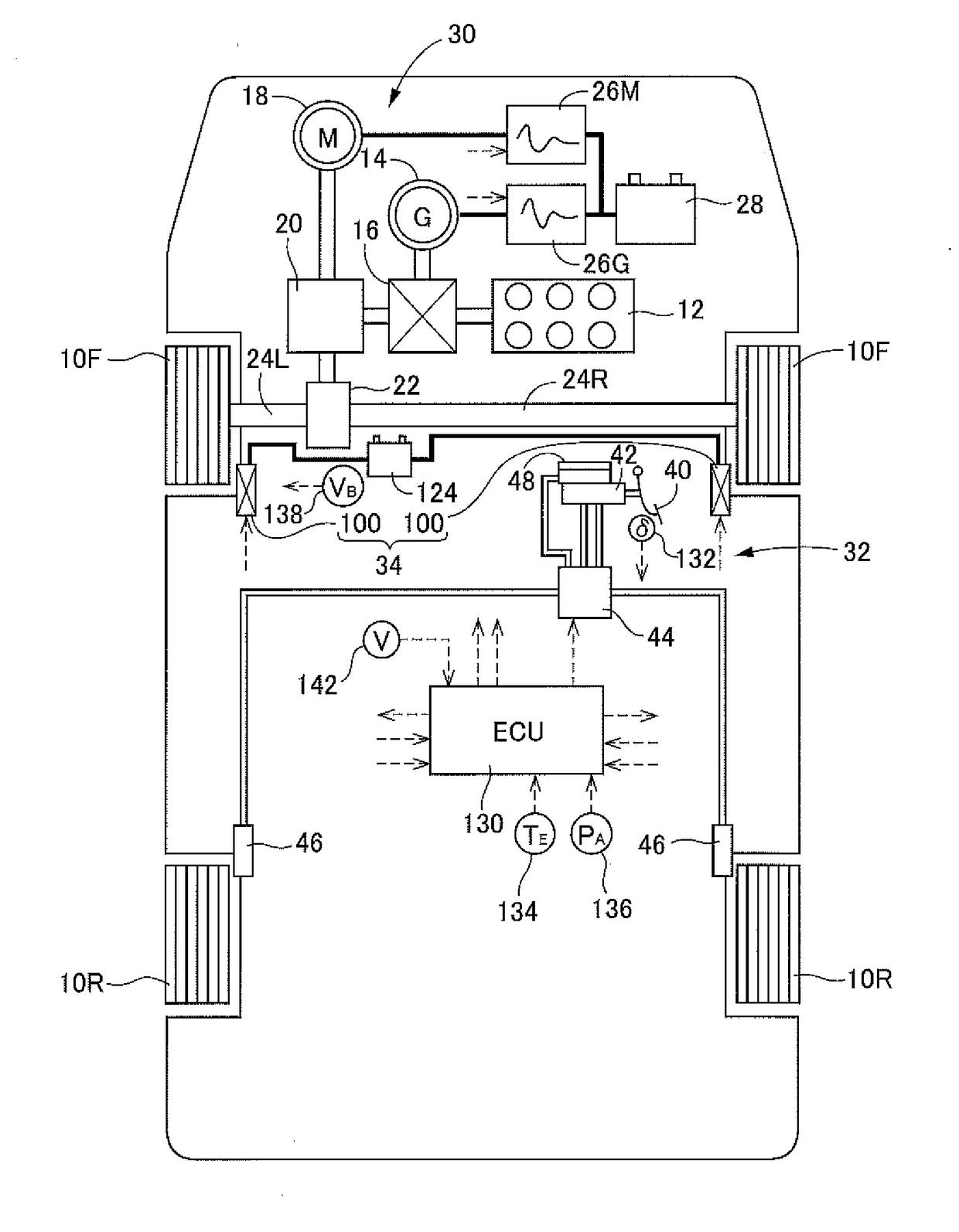
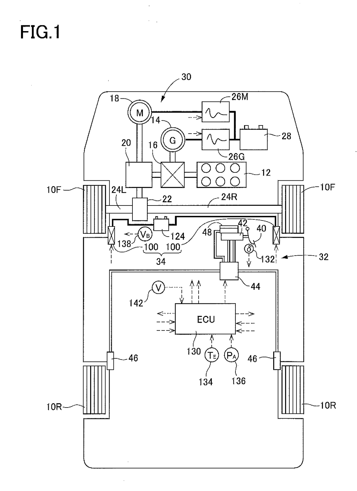
[0107]As schematically shown in FIG. 1, a vehicle on which a vehicle brake system according to a first embodiment is installed is a hybrid vehicle having two front wheels 10F and two rear wheels 10R, and the two front wheels 10F are drive wheels. The vehicle drive system is first explained. The vehicle drive system installed on the present vehicle includes an engine 12 as a drive source, a generator 14 that mainly functions as an electric generator, a power-distribution mechanism 16 to which the engine 12 and the generator 14 are coupled, and an electric motor 18 as another drive source.

[0108]The power-distribution mechanism 16 has a function of distributing rotation of the engine 12 to rotation of the generator 14 and rotation of an output shaft. The electric motor 18 is coupled to the output shaft via a reduction mechanism 20 functioning as a speed reducer. Rotation of the output shaft is transmitted to the front left and ...

embodiment 2

A. Structure of Vehicle Brake System

[0156]As shown in FIG. 14, a vehicle on which a brake system according to a second embodiment is installed is not a hybrid vehicle. A vehicle drive system installed on the vehicle of the second embodiment includes the engine 12 as the drive source, a transmission mechanism 150, the differential mechanism 22, and the drive shafts 24L, 24R and is configured to drive the right and left front wheels 10F. The present brake system includes the hydraulic brake device 32 and the electric brake device 34 without including the regenerative brake device. In the following explanation, the same reference numerals as used in the first embodiment are used to identify devices and constituent components of the second embodiment having the same functions as the devices and constituent components of the first embodiment, and a detailed explanation thereof is dispensed with. The vehicle brake system according to this second embodiment also enjoys the advantage of the...

embodiment 3

A. Outline of Vehicle Drive System and Vehicle Brake System

[0172]As schematically shown in FIG. 18, a vehicle on which a vehicle brake system according to a third embodiment is installed (hereinafter referred to as “the vehicle of the third embodiment” where appropriate) is a hybrid vehicle like the vehicle on which the vehicle brake system according to the first embodiment is installed (hereinafter referred to as “the vehicle of the first embodiment”). A vehicle drive system according to the third embodiment is substantially similar to the vehicle drive system of the first embodiment. In the following explanation, the same reference numerals as used in the first embodiment are used to identify constituent components of the third embodiment having the same functions as the constituent components of the first embodiment, and a detailed explanation thereof is dispensed with. Unlike the control in the vehicle drive system installed on the vehicle of the first embodiment, the control in...


PUM


Abstract

A vehicle brake system, including: a brake operation member to be operated by a driver of a vehicle; a hydraulic brake device provided for one of a front wheel and a rear wheel and configured to generate a hydraulic braking force in accordance with an operation of the brake operation member, the hydraulic braking force depending on a pressure of a working fluid; and an electric brake device provided for the other of the front wheel and the rear wheel and configured to generate an electric braking force in accordance with the operation of the brake operation member, the electric braking force depending on a motion of an electric motor.

Description

CROSS REFERENCE TO RELATED APPLICATION[0001]The present application claims priority from Japanese Patent Application Nos. 2016-026517, 2016-108552, 2016-148414, and 2016-188519 which were respectively filed on Feb. 16, 2016, May 31, 2016, Jul. 28, 2016, and Sep. 27, 2016, the disclosure of which is herein incorporated by reference in its entirety.BACKGROUND[0002]Technical Field[0003]The present disclosure relates to a brake system configured to brake a vehicle.[0004]Description of Related Art[0005]Many of conventional vehicle brake systems are constituted by a hydraulic brake device as disclosed in JP-A-2004-338582, for instance. Some vehicle brake systems are constituted by an electric brake device as disclosed in JP-A-2001-263395, for instance.SUMMARY[0006]The hydraulic brake device has the advantage of high reliability, and the electric brake device has the advantage of good response. These brake devices, however, have respective drawbacks. An aspect of the disclosure provides a ...

Claims


Application Information

Patent Timeline
IPC IPC(8): B60L7/26B60T13/58B60T13/14B60T8/172
CPCB60L7/26B60T8/172B60T2270/604B60T13/142B60T2210/30B60T13/586B60T13/12B60T13/74B60T2270/60B60T8/267B60T8/348B60T8/4081B60T8/26B60T13/588B60T13/745
Inventor YAMAMOTO, NAOKITAKAHASHI, YU
Owner TOYOTA JIDOSHA KK
Why Eureka
Try Eureka