Electro-pneumatic gas turbine engine motoring system for bowed rotor engine starts

Inactive Publication Date: 2017-08-17
HAMILTON SUNDSTRAND CORP
View PDF6 Cites 52 Cited by
  • Summary
  • Abstract
  • Description
  • Claims
  • Application Information

AI Technical Summary

Benefits of technology

[0018]In addition to one or more of the features described above, or as an alternative, further embodiments of the method of cooling a gas turbine engine may include: controlling, using a motor controller, operation of the electric drive motor, the motor controller being configured to command the electric drive motor to rotate the rotational components at a selected angular velocity for a selected period of time.
[0019]In addition to one or more of the features described above, or as an alternative, further embodiments of the method of cooling a gas turbine engine may include: detecting a failure in a starter air valve prior to rotating the gas turbine engine with the electric drive motor, the starter air valve being fluidly connected to the electro-pneumatic starter and configured to provide air to the electro-pneumatic starter.
[0020]In addition to one or more of the features described above, or as an alternative, further embodiments of the method of cooling a gas t

Problems solved by technology

These tighter clearances can result in compressor blade tips and turbine blade tips rubbing on the engine cases if the engine core bows as it cools down between flights and an engine start is attempted.
This causes blade tip clearance between the engine case and blades of the compressor and turbine to decrease as the engine shafts and cases bow temporarily due to uneven thermal conditions.
The problem is how to motor the engine at very specific speeds for up to four minutes prior to engine start, and/or how to motor

Method used


Image

  • Electro-pneumatic gas turbine engine motoring system for bowed rotor engine starts
  • Electro-pneumatic gas turbine engine motoring system for bowed rotor engine starts
  • Electro-pneumatic gas turbine engine motoring system for bowed rotor engine starts

Examples


Embodiment Construction

[0031]A detailed description of one or more embodiments of the disclosed apparatus and method are presented herein by way of exemplification and not limitation with reference to the Figures.

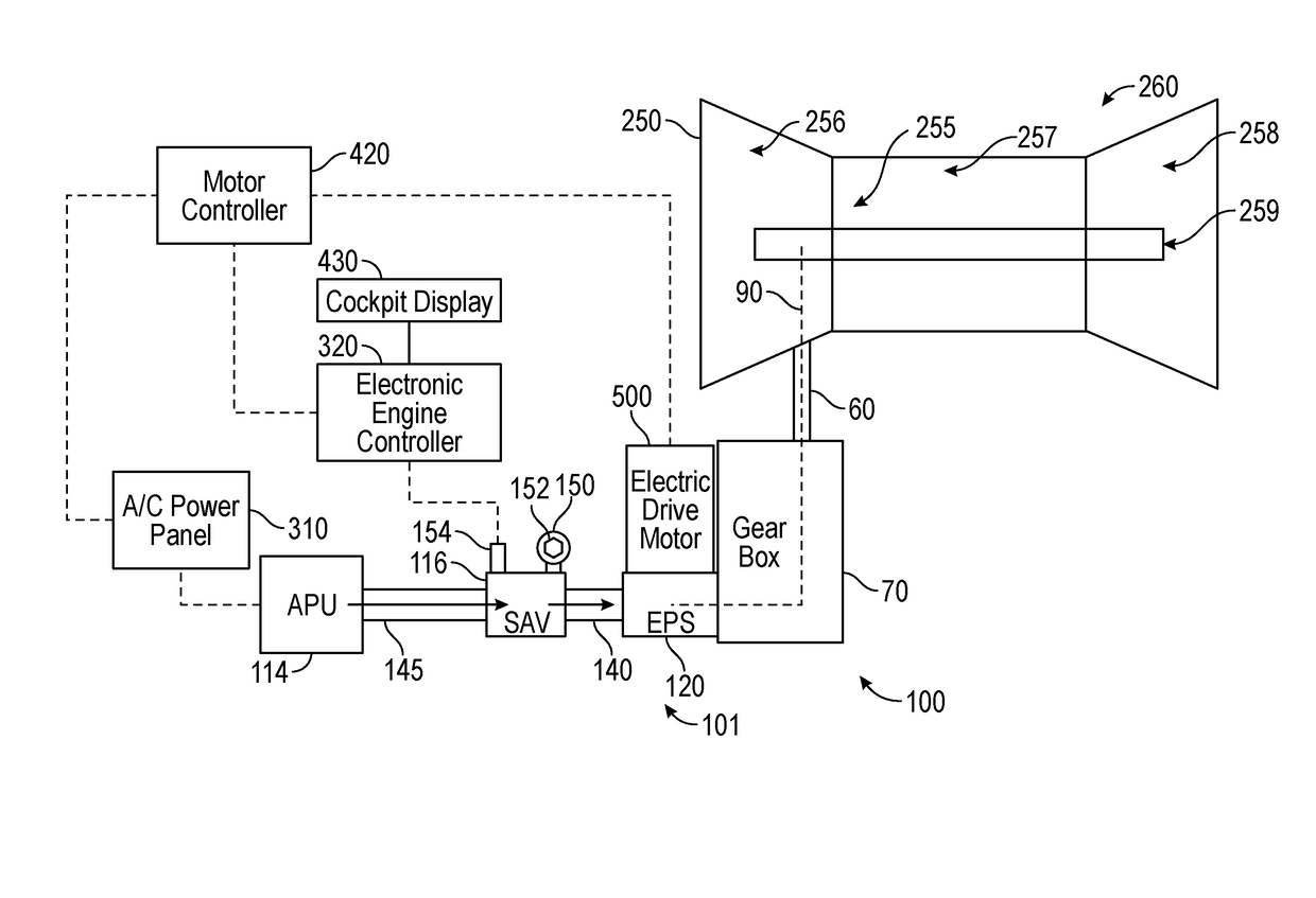
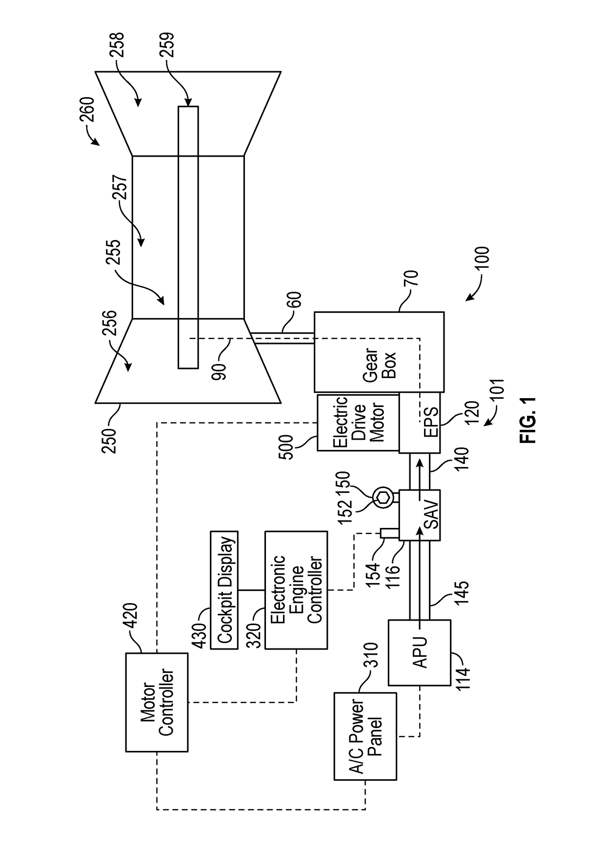
[0032]Various embodiments of the present disclosure are related to a bowed rotor start mitigation system in a gas turbine engine. Embodiments can include using an electro-pneumatic starter to control a rotor speed of a gas turbine engine to mitigate a bowed rotor condition using a cool-down motoring process. Cool-down motoring may be performed by running an engine starting system at a lower speed with a longer duration than typically used for engine starting using an electro-pneumatic starter to maintain a rotor speed and / or profile. Cool-down motoring (engine bowed rotor motoring) may be performed by the electro-pneumatic starter, which may rotate the gas turbine engine continuously between about 0-3000 RPM (engine core speed).

[0033]Referring now to the figures, FIG. 1 shows a block diagram of a...


PUM


Abstract

An engine starting system for a gas turbine engine is provided, the engine starting system comprising: a gas turbine engine including rotational components comprising an engine compressor, an engine turbine, and a rotor shaft operably connecting the engine turbine to the engine compressor, wherein each rotational component is configured to rotate when any one of the rotational components is rotated; an electro-pneumatic starter operably connected to at least one of the rotational components, the electro-pneumatic starter being configured to rotate the rotational components; an electric drive motor operably connected to the electro-pneumatic starter, the electric drive motor being configured to rotate the rotational components through the electro-pneumatic starter; and a motor controller in electronic communication with the electric drive motor, the motor controller being configured to command the electric drive motor to rotate the rotational components at a selected angular velocity for a selected period of time.

Description

CROSS-REFERENCE TO RELATED APPLICATIONS[0001]This application claims the benefit of U.S. provisional patent application Ser. No. 62 / 294,554, filed Feb. 12, 2016, the entire contents of which are incorporated herein by reference.BACKGROUND[0002]The embodiments herein generally relate to gas turbine engines and more specifically, systems and method for cooling gas turbine engines.[0003]Aircraft gas turbine engines are being designed with tighter internal clearances between engine cases and blades of the compressor and turbine to increase efficiency and reduce fuel burn. These tighter clearances can result in compressor blade tips and turbine blade tips rubbing on the engine cases if the engine core bows as it cools down between flights and an engine start is attempted.[0004]After engine shutdown, the main shafts, compressor disks, turbine disks and other parts with large thermal mass cool at different rates. The heat rises to the top of the engine allowing the lower portions of these ...

Claims


Application Information

Patent Timeline
IPC IPC(8): F02C7/27F02N11/08F02C7/36
CPCF02C7/27F02C7/36F02N11/0859F05D2260/4031F05D2220/50F05D2230/60F05D2260/85F02N11/0862F02C7/277Y02T50/60F05D2270/112F01D19/02F01D25/12F01D15/10
Inventor PECH, JOHN T.
Owner HAMILTON SUNDSTRAND CORP
Why Eureka
Try Eureka