Holographic see-through optical device, stereoscopic imaging system, and multimedia head mounted system

a technology of optical devices and see-through optical devices, applied in the field of optical systems, can solve problems such as the need for high-precision micro-mechanical actuators

Active Publication Date: 2017-08-17
SAMSUNG ELECTRONICS CO LTD
View PDF10 Cites 60 Cited by
  • Summary
  • Abstract
  • Description
  • Claims
  • Application Information

AI Technical Summary

Benefits of technology

[0020]According to one or more exemplary embodiments, a stereoscopic imaging system in which any of the holographic see-through optical devices are arranged at eyes of a viewer, respectively.
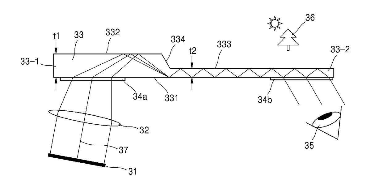
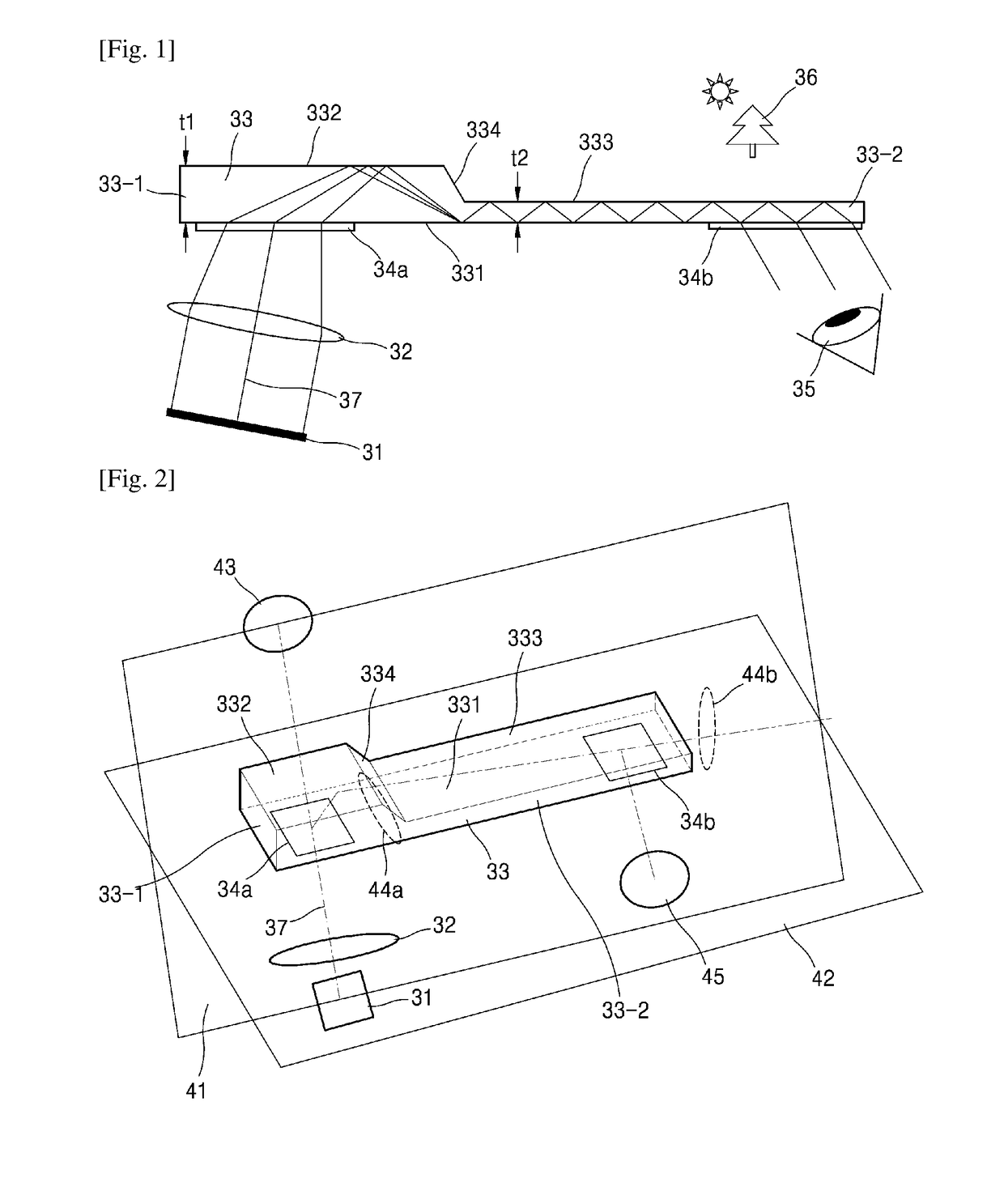
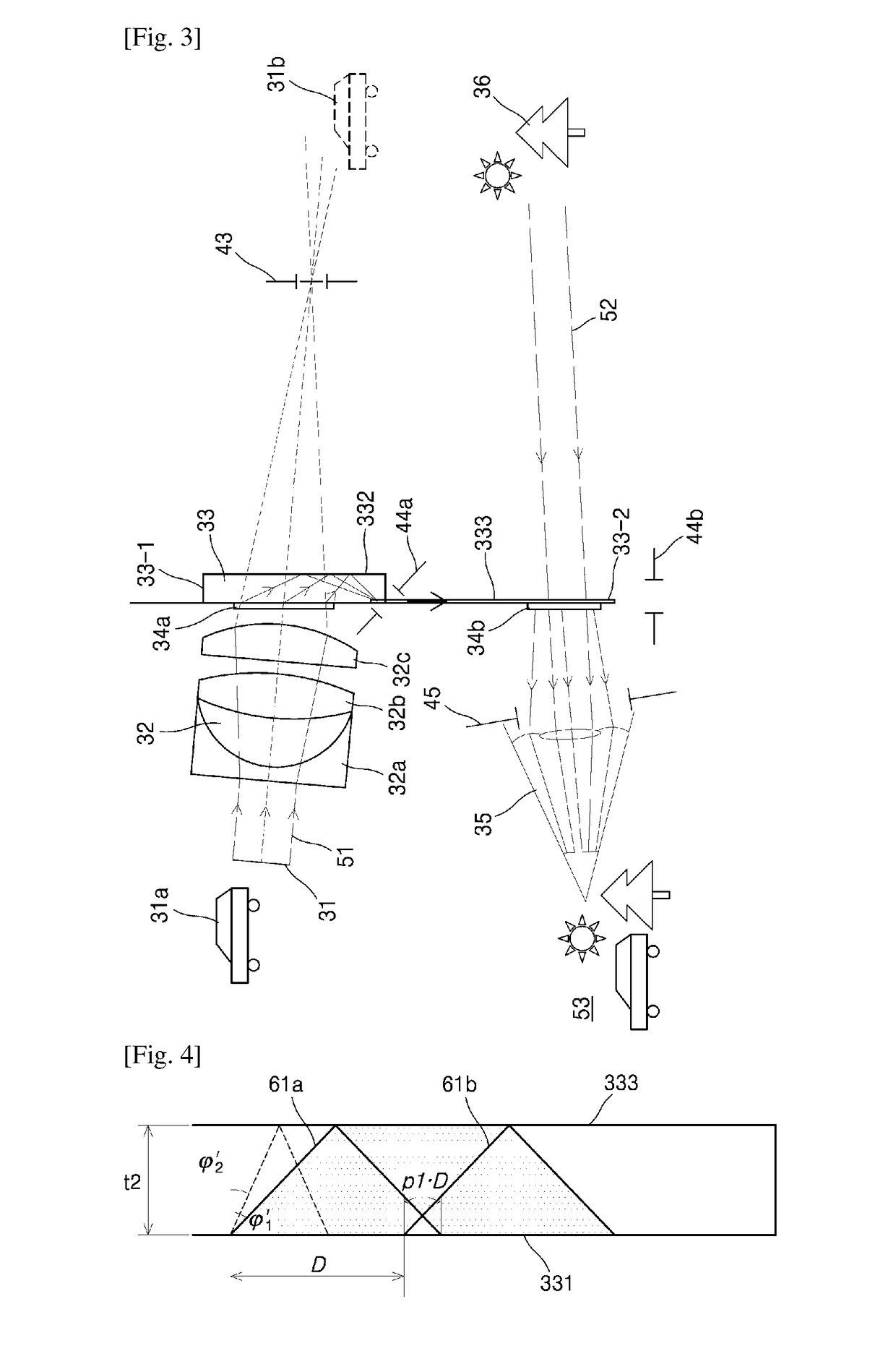
[0021]According to one or more exemplary embodiments, a multimedia head mounted system enabling a user to watch surrounding environment combined with displayed content, the multimedia head mounted system includes a micro display, which generates an image; a relay optical system, which relays an image generated by the micro display; at least one waveguide including at least two portions having different thicknesses or different refractive indexes; at least on first holographic optical element arranged; at least one of x second holographic optical element; an integrated processor for handling content to be displayed to the user; and earpieces to be mounted on the head of the user, wherein an exit pupil is formed at a location apart from the first portion of the waveguide, the first holographic optical element combines light beams at the first portion of the waveguide and relays the exit pupil to a region at which the first portion and the second portion of the waveguide meet each other, the exit pupil propagates in the second portion of the waveguide via total internal reflection to retransmit light beams, and the second holographic optical element combines light beams from the waveguide and relays the exit pupil at a location apart from the second portion of the waveguide.

Problems solved by technology

The disadvantage of these systems is the need for high-precision micro-mechanical actuators.

Method used


Image

  • Holographic see-through optical device, stereoscopic imaging system, and multimedia head mounted system
  • Holographic see-through optical device, stereoscopic imaging system, and multimedia head mounted system
  • Holographic see-through optical device, stereoscopic imaging system, and multimedia head mounted system

Examples


Embodiment Construction

[0040]Reference will now be made in detail to exemplary embodiments, examples of which are illustrated in the accompanying drawings, wherein like reference numerals refer to like elements throughout. In this regard, the present exemplary embodiments may have different forms and should not be construed as being limited to the descriptions set forth herein. Accordingly, the exemplary embodiments are merely described below, by referring to the figures, to explain aspects of the present description. Expressions such as “at least one of,” when preceding a list of elements, modify the entire list of elements and do not modify the individual elements of the list.

[0041]In the drawings, the thicknesses of layers and regions are exaggerated for clarity. It will also be understood that when a layer is referred to as being “on” another layer or substrate, it can be directly on the other layer or substrate, or intervening layers may also be present. Like reference numerals in the drawings denote...


PUM


Abstract

A holographic see-through optical device, a stereoscopic imaging system including the same, and a multimedia head mounted system are provided. The holographic see-through optical device includes a micro display; a relay optical system, which relays an image generated by the micro display; at least one waveguide comprising at least two portions having different thicknesses or different refractive indexes; at least one first holographic optical element, which is arranged at one of the two portions; and at least one second holographic optical element, which is arranged at the other one of the two portions.

Description

TECHNICAL FIELD[0001]One or more exemplary embodiments relate to an optical system, and more particularly, to a holographic see-through optical device for displaying a combination of a virtual image and a see-through view, a stereoscopic imaging system including the same, and a multimedia head mounted system.BACKGROUND ART[0002]Most of the known optical devices of augmented reality are based on a combination of eyepiece eyepieces to enlarge an image formed by LCDs, LCoSs, CRTs, OLEDs, or other spatial light modulators having compact size and image combiners are based on, for example, a beam-splitting cube or a semitransparent plate. In some optical devices of augmented reality that reduce the size of a device, a scanning module is used, wherein a two-dimensional image is formed by sequentially field scanning by narrow beam. The disadvantage of these systems is the need for high-precision micro-mechanical actuators.DISCLOSURE OF INVENTIONTechnical Problem[0003]A flat waveguide is use...

Claims


Application Information

Patent Timeline
Patent Type & Authority Applications(United States)
IPC IPC(8): G02B27/01G02B5/32G02B6/34
CPCG02B27/0172G02B6/34G02B5/32G02B2027/0178G02B2027/0174G02B2027/014G02B2027/0134G02B27/0081G02B2027/0118G03H2001/2226G02F1/025G02B5/18G02B6/00
Inventor PISKUNOV, DMITRY EVGENIEVICHMOROZOV, ALEKSANDER VIKTOROVICHPOPOV, MIKHAIL VYACHESLAVOVICHZAKHAROVA, NATALIA VLADIMIROVNAMURAVEV, NIKOLAY VIKTOROVICH
Owner SAMSUNG ELECTRONICS CO LTD
Why Eureka
Try Eureka