Vehicle Fairing with Brake Cooling System

Inactive Publication Date: 2017-08-24
KRON STEVEN +1
View PDF0 Cites 23 Cited by
  • Summary
  • Abstract
  • Description
  • Claims
  • Application Information

AI Technical Summary

Benefits of technology

[0008]Each axle is also covered by a flat panel, such that this volume of air is confined to the space beneath. A brake cooling system is mounted to both of these panels, and is comprised of a pair of rotating panels, which protrude downward such that their surfaces are parallel to the direction of the airflow. When the brakes are engaged, these panels rotate towards the cente

Problems solved by technology

When the elements which cause drag are essential structural components, they cannot be removed, displaced, or dramatically altered.
In particular, the axles and associated

Method used


Image

  • Vehicle Fairing with Brake Cooling System
  • Vehicle Fairing with Brake Cooling System
  • Vehicle Fairing with Brake Cooling System

Examples


Embodiment Construction

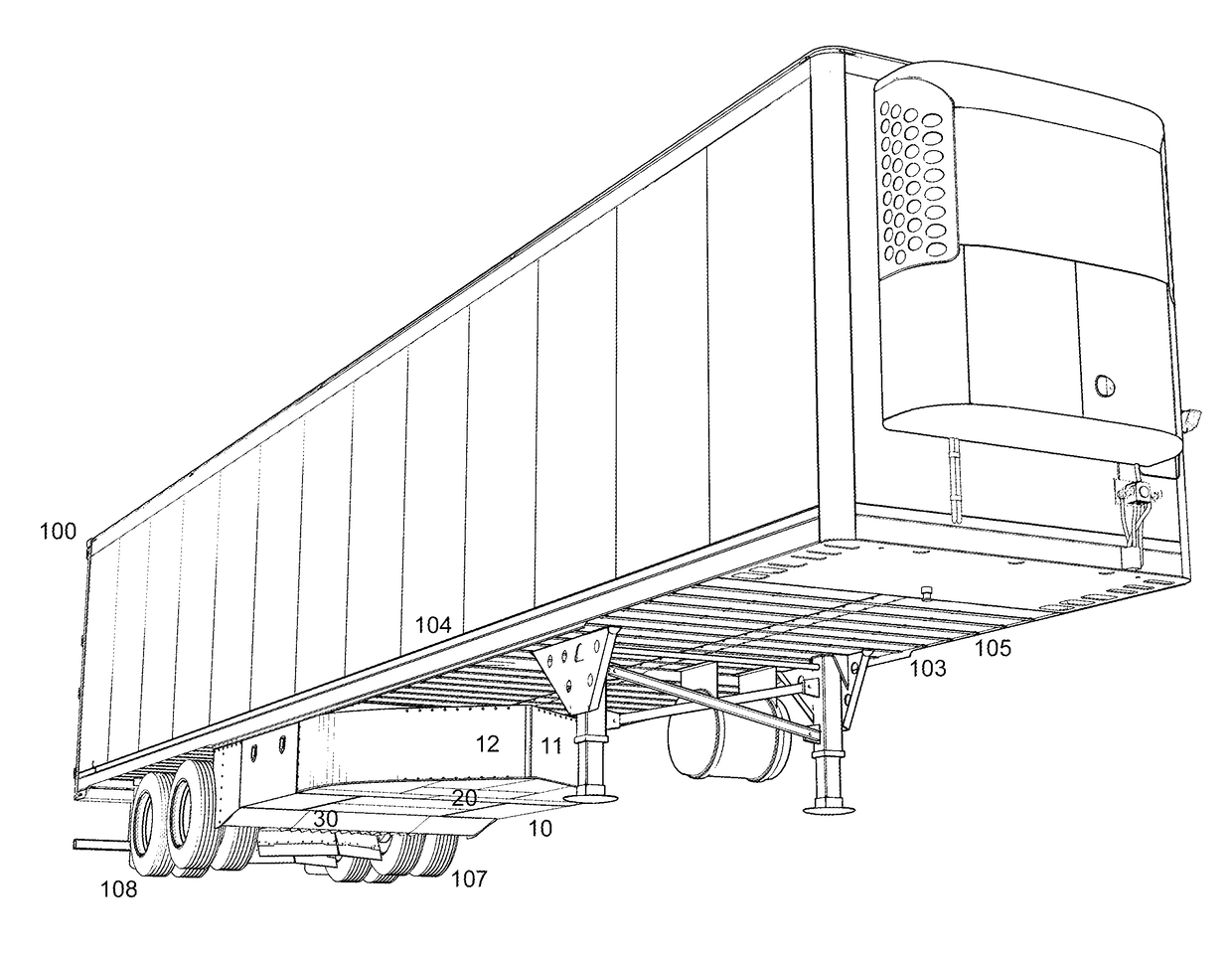
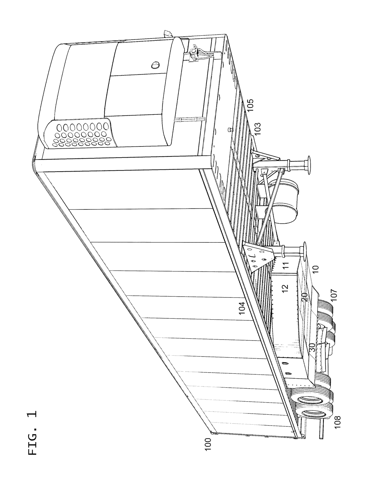
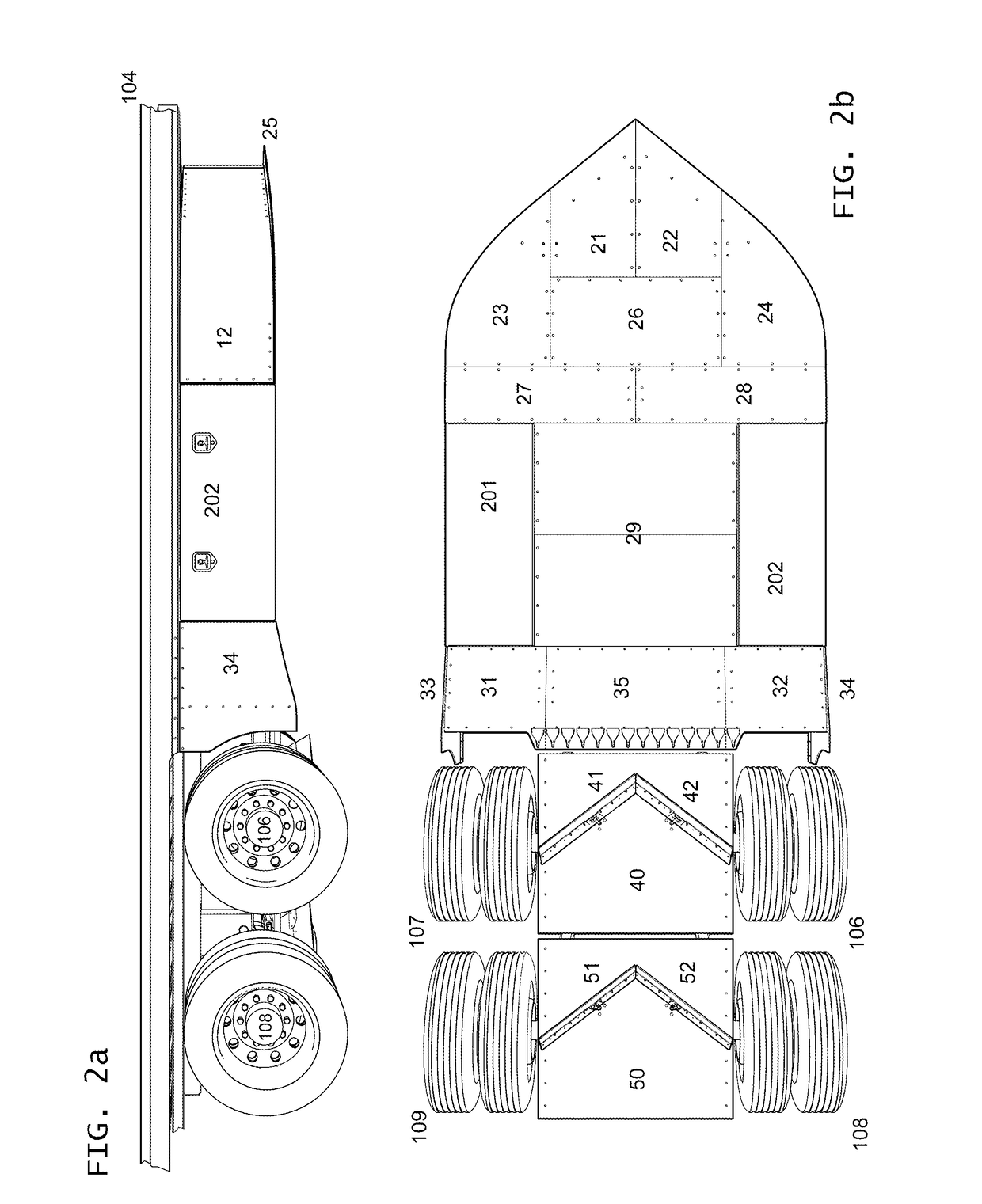
[0025]The invention consists of fairing 10 mounted to the underside of a trailer and brake cooling systems 40 and 50 attached to both axles. The basic shape of the fairing is a wedge that spans the full width of trailer 100, which curves towards the outside edge and tapers to a flat surface parallel to the sides of the trailer. In the exemplary embodiment, this teardrop shaped wedge is formed by directionally flexible fiberglass composite sheets 11 and 12, measuring eight feet by two feet. They are curved inward from the outer edge of the trailer and angled inwards so that they meet along their forward edges.

[0026]These sheets are joined along this edge by aluminum angle 150 and a series of rivets. Aluminum angles are also riveted to the inside of the sheet, with angles 151 and 152 along the top edge, through which panels 11 and 12 are attached to the underside of the trailer. Angles 153 and 154, which are riveted to the bottom edge, further define the curvature of panels 11 and 12 ...


PUM


Abstract

The primary purpose of this device is to reduce the fuel consumption of heavy trucks by improving airflow along the underside of a trailer, by way of a fairing mounted forward of the axles. This fairing is a teardrop shaped wedge with a flat bottom surface, which directs air towards the sides of the vehicle, while allowing a smaller volume to flow beneath the fairing such that it will clear the axles. Each axle is also covered by a flat panel, such that air will continue to travel smoothly beneath them. Attached to each panel is a brake cooling system, which consists of a pair of panels protruding downward, with their surfaces parallel to the direction of airflow. When the brakes are engaged, these panels rotate towards the center in an angled configuration, which redirects air towards the drums during and after braking, cooling them quickly and efficiently.

Description

BACKGROUND OF THE INVENTION[0001]Of the factors influencing the fuel economy of semi-trucks, aerodynamics is the field in which the greatest improvements might be most readily made. Of the two types of aerodynamic drag, friction drag and pressure drag, pressure drag has a particularly significant impact on heavy trucks, accounting for as much as 90% of drag force. On a standard, unmodified truck and trailer, approximately one third of this pressure drag is caused by the vehicle undercarriage.[0002]When the elements which cause drag are essential structural components, they cannot be removed, displaced, or dramatically altered. Instead, aerodynamic fairings can be attached to the vehicle to improve airflow, thereby reducing drag and consequently fuel consumption.[0003]In particular, the axles and associated parts of the undercarriage are prohibitive to smooth, stable airflow. A fairing installed forward of the tires can prevent most air from ever reaching the axles, minimizing relate...

Claims


Application Information

Patent Timeline
IPC IPC(8): B62D35/00F15D1/00B62D63/08B60T5/00B62D35/02
CPCB62D35/001B60T5/00B60Y2400/408B62D63/08F15D1/009B62D35/02Y02T10/88B60T7/20F16D65/128F16D65/847
Inventor KRON, STEVENKRON, ERIC THOMAS
Owner KRON STEVEN
Why Eureka
Try Eureka