

Fuel cell power pack for multicopter
a multi-copter and fuel cell technology, applied in the direction of electrochemical generators, batteries, transportation and packaging, etc., can solve the problems of limited flight distance or its use, difficult to meet the requirement of lightweightness, and too loud nois
- Summary
- Abstract
- Description
- Claims
- Application Information
AI Technical Summary
Benefits of technology
Problems solved by technology
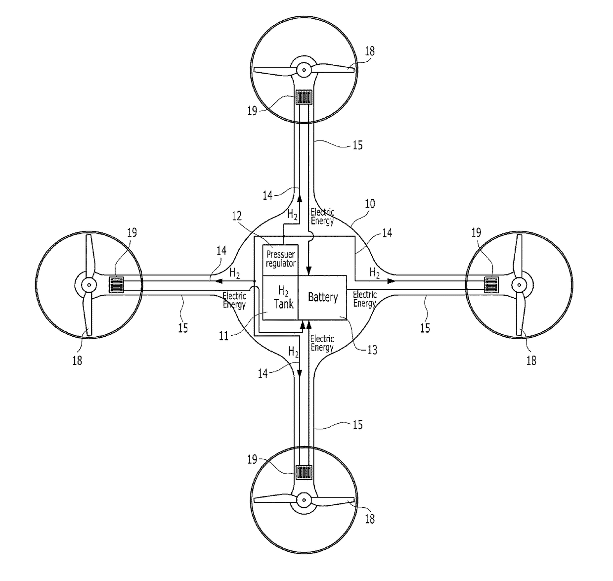
Method used
Image

Examples
first embodiment
[0067]FIG. 5 is an enlarged side view showing the front end of an arm on which a fuel cell stack of a fuel cell power pack according to the present invention is mounted, FIG. 6 is a plan view showing the front end of an arm of FIG. 5 from the top, and FIG. 7 is a cross-sectional view showing the front end of an arm of FIG. 6 taken along the cutting line A-A.
[0068]Referring to FIGS. 5 to 7, one or more fuel cell stacks 19 applied to a first embodiment are installed on the arm in an area S1 affected by the thrust of the rotating blade 18. Here, the area affected by the thrust does not mean only the inside of a geometric circular trajectory drawn by the wing tip of the rotating blade 18 as shown in FIG. 6 for example, but means an area including all the areas aerodynamically affected by the thrust, beyond the boundary of the trajectory.
[0069]The fuel cell stack 19 according to a first embodiment may be a configuration of disposing several unit cells 192 to be stacked inside the housing...
second embodiment
[0074]FIG. 8 is an enlarged side view showing the front end of an arm on which a fuel cell stack of a fuel cell power pack according to the present invention is mounted.
[0075]Referring to FIG. 8, one or more fuel cell stacks 19 may be installed on the arm 15 to be close to the outer portion of the tip 180 of the rotating blade 18. Here, it is most preferable to understand the expression of ‘on the arm 15’ as the top surface of the arm 15 facing the rotating blade 18. However, it is not limited to the top surface, but may even include both side surfaces of the arm 15.
[0076]The fuel cell stack 19 of the second embodiment is driven by a wing tip vortex, which is a wing tip swirl generated on the side surface of the blade when the rotating blade 18 rotates. That is, since the fuel cell stack 19 is driven by a lateral side mobile air current generated by the wing tip swirl generated by the rotating blade 18, electrical energy is produced, and cooling down of the fuel cell stack is implem...
third embodiment
[0080]FIG. 9 is an enlarged side view showing the front end of an arm on which a fuel cell stack of a fuel cell power pack according to the present invention is mounted.
[0081]The third embodiment of FIG. 3 is characterized in that the fuel cell stack 19 is disposed under the driving motor 17 positioned at the front end of the arm 15. Specifically, the fuel cell stack 19 is disposed under the driving motor 17 inside the motor housing 16 positioned at the front end of the arm 15, and the fuel cell stack 19 operates by the descending air current passing through the motor housing 16, out of the entire descending air current generated by the rotating blade 18.
[0082]The motor housing 16 applied to the third embodiment may be a cylindrical structure with an open top and an open bottom. Preferably, the motor housing 16 may be a hollow tube shape having an open top and an open bottom, which is aerodynamically designed not to affect the thrust of the multicopter and shaped in a spindle having...
PUM
| Property | Measurement | Unit |
|---|---|---|
| electrical energy | aaaaa | aaaaa |
| area | aaaaa | aaaaa |
| thrust | aaaaa | aaaaa |
Abstract
Description
Claims
Application Information