
Method and system for evaluating and predicting sprocket tooth wear

Active Publication Date: 2017-08-24
ANDRITZ INC
View PDF0 Cites 9 Cited by
  • Summary
  • Abstract
  • Description
  • Claims
  • Application Information

AI Technical Summary

Benefits of technology

The invention allows people to see the wear and tear of sprocket teeth while the sprocket is still at the production facility. This can be helpful in identifying areas of wear and determining when to replace the sprocket. The sprocket gauge can be made from various materials and is designed to maintain its shape.

Problems solved by technology

Applicant has discovered that wood yards shafts and sprockets in chain conveyors generally benefit from maintenance between three to five year intervals, but has experienced difficulty convincing customers to repair or replace shafts and sockets.
Without being bounded by theory, Applicant believes that this problem is due in part to a lack of a method and system that minimally disrupts production.

Method used


Image

  • Method and system for evaluating and predicting sprocket tooth wear
  • Method and system for evaluating and predicting sprocket tooth wear
  • Method and system for evaluating and predicting sprocket tooth wear

Examples


Embodiment Construction

[0026]The following detailed description of the preferred embodiments is presented only for illustrative and descriptive purposes and is not intended to be exhaustive or to limit the scope and spirit of the invention. The embodiments were selected and described to best explain the principles of the invention and its practical application. A person of ordinary skill in the art will recognize that many variations can be made to the invention disclosed in this specification without departing from the scope and spirit of the invention. Except as otherwise stated, corresponding reference characters indicate corresponding parts throughout the several views. Although the drawings represent embodiments of various features and components according to the present disclosure, the drawings are not necessarily to scale and certain features may be exaggerated in order to better illustrate embodiments of the present disclosure, and such exemplifications are not to be construed as limiting the scop...


PUM


Abstract

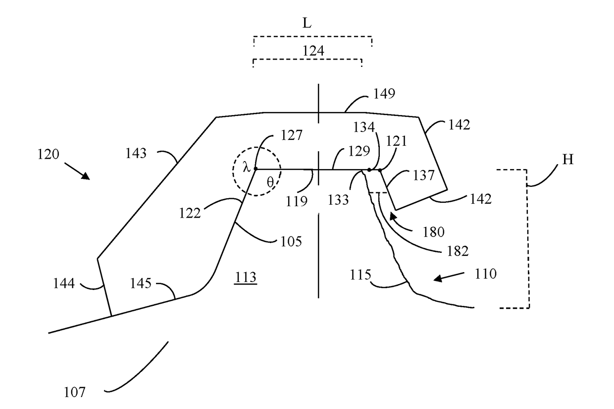
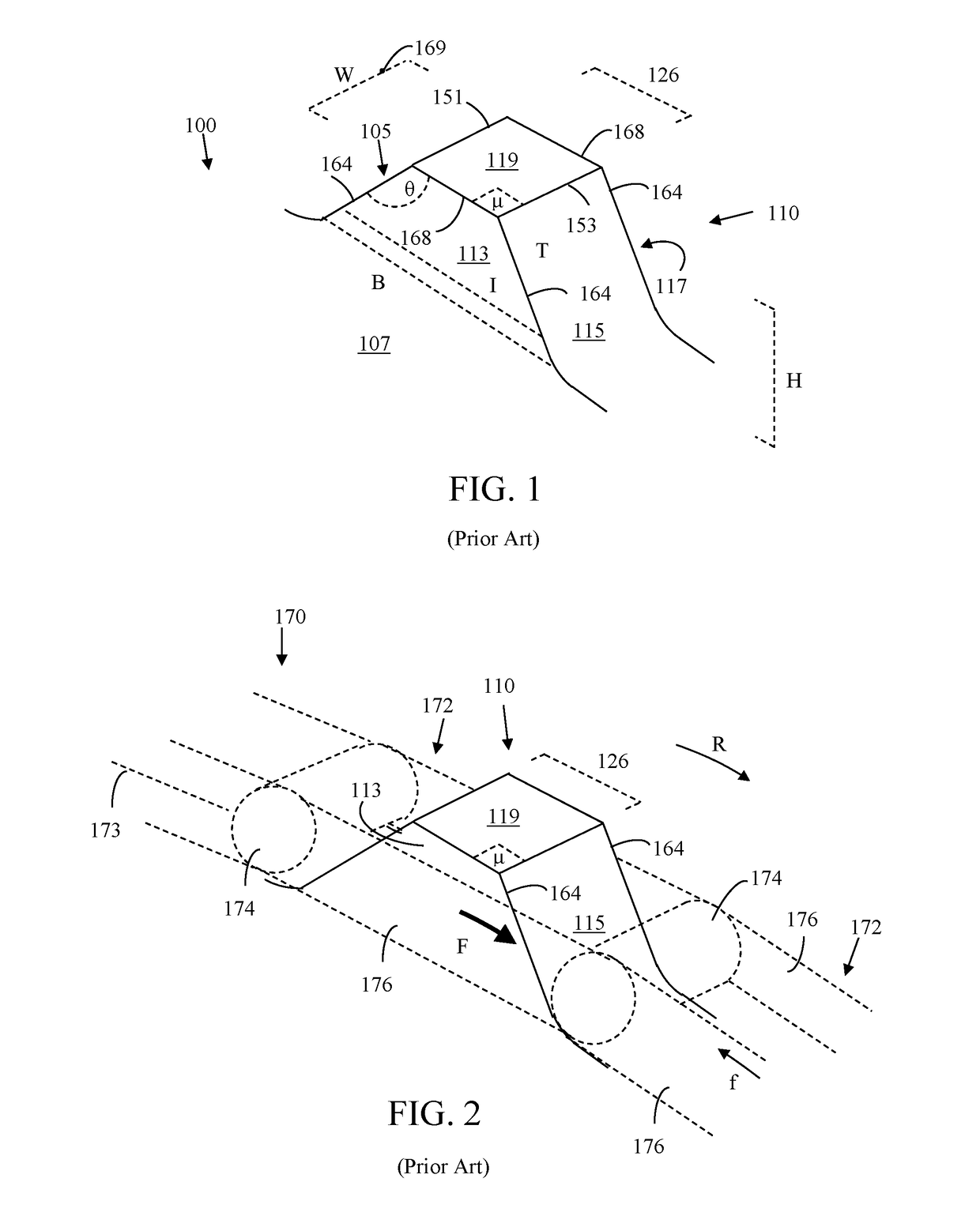
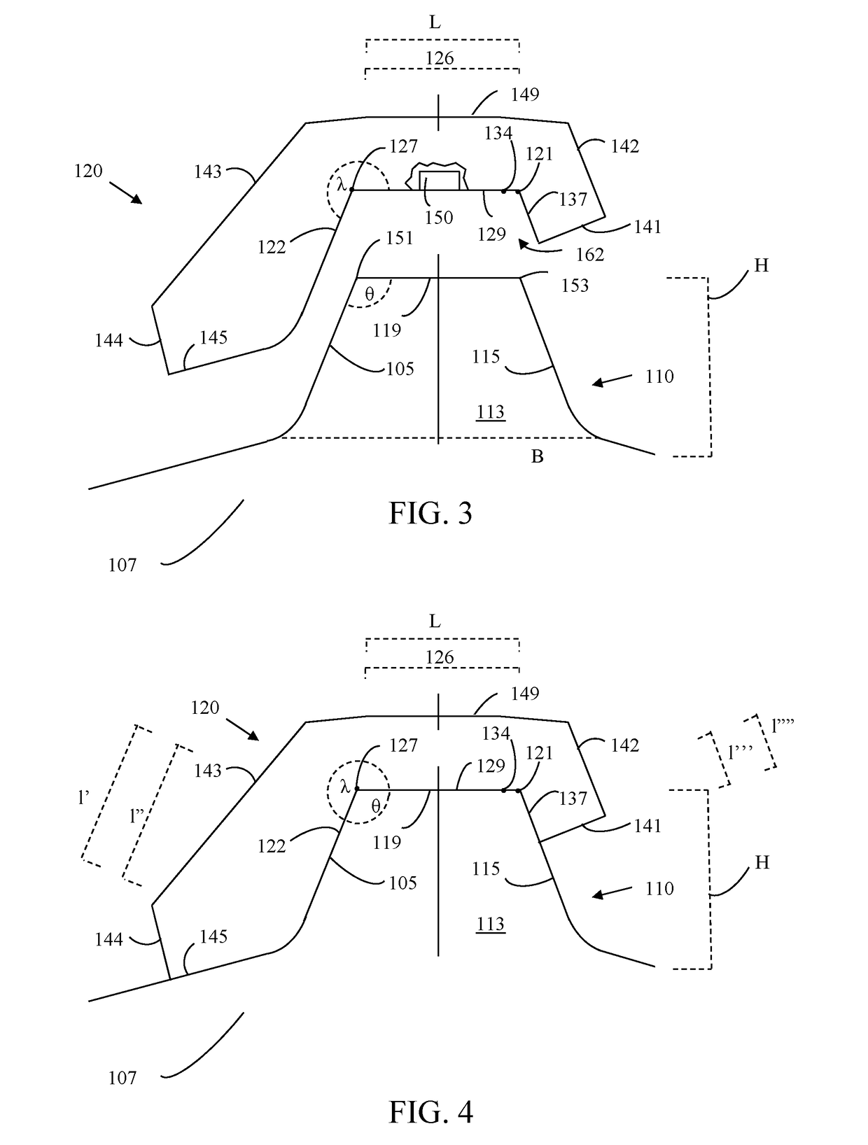
An exemplary method may comprise: ascertaining an original distance between a first tooth face and a second tooth face of a sprocket tooth, wherein the sprocket tooth comprises two tooth faces extending from a sprocket core and terminating in a top of the sprocket tooth, wherein an original distance separates the two tooth faces, placing a sprocket gauge on the sprocket tooth, wherein the sprocket gauge comprises: a bottom, and two gauge faces extending from the bottom of the sprocket gauge, wherein the bottom of the sprocket gauge is disposed upon the top of the sprocket tooth and the first gauge face is disposed adjacently on the first tooth; and comparing the original distance defined by the sprocket gauge with an actual distance between the first tooth face and the second tooth face.

Description

CROSS-RELATED APPLICATION[0001]This application is a Non-Provisional Application claiming the benefits of U.S. Provisional Application Ser. No. 62 / 298,616 filed on Feb. 23, 2016, the entirety of which is incorporated herein by reference.BACKGROUND OF THE INVENTION[0002]1. Technical Field[0003]The present disclosure relates generally to a method for evaluating gear wear on chain conveyors and particularly to evaluating gear wear on chain conveyors in the pulp and paper industry and the recycling industry.[0004]2. Related Art[0005]In the pulp and paper industry and the recycling industry, equipment manufacturers periodically evaluate the condition and performance of the equipment sold to customers. In pulp and paper wood yards, for example, manufacturers preliminary inspect a wood yard several months before an annually scheduled maintenance shutdown. These intermediate, preliminary inspections allow the equipment manufactures to provide the wood yard operators with data and allow the ...

Claims


Application Information

Patent Timeline
IPC IPC(8): F16H57/01G01B5/02
CPCF16H57/01F16H2057/012G01B5/02B65G23/06G01B3/38B65G2207/48
Inventor LINTUNEN, TIMO
Owner ANDRITZ INC
Learn More