
Methods for enhancing the dehumidification of heat pumps

Active Publication Date: 2017-08-24
AIL RES
View PDF8 Cites 1 Cited by
  • Summary
  • Abstract
  • Description
  • Claims
  • Application Information

AI Technical Summary

Benefits of technology

The patent describes a valve that can control the flow of a liquid or gas. This valve can be adjusted to control the amount of each flow and create a balance between them. This technology can be useful in various applications such as industrial processes, chemical synthesis, and manufacturing.

Problems solved by technology

Unfortunately, heat pumps are not efficient latent cooling devices.
This process of overcooling and reheating wastes energy and increases the cost to maintain comfortable indoor conditions.
Heat pumps that augment their latent cooling using technology described in the either the Griffiths, Forkosh, Vandermeulen or Dinnage patents will all have fundamental performance limitations.
These high flooding rates require large pumps with high power draws.
They also produce large air-side pressure drops in the flooded beds that increase the heat pump's fan power.
These two heat transfer loops both increase the heat pump's power use and degrade performance by introducing temperature drops that force the heat pump's thermal sink to run at a lower temperature and its thermal source to run at a higher temperature.
The source of the limitations inherent in a heat pump that uses the Dinnage technology is the solid desiccant rotor.
In particular:(a) There is no simple way to pre-cool the warm regeneration (i.e., water desorption) sector of the desiccant wheel as it rotates into the air stream that is to be dehumidified.
The heat stored in the mass of the wheel is therefore transferred to this air stream, thereby reducing the cooling effect provided by the air conditioner.
A heat pump that applies the technology in the Lowenstein patent also has important limitations, although the limitations are not fundamental, rather centering on the practical concerns of the investment in capital equipment required to manufacture a new heat pump design.

Method used


Image

  • Methods for enhancing the dehumidification of heat pumps
  • Methods for enhancing the dehumidification of heat pumps
  • Methods for enhancing the dehumidification of heat pumps

Examples


Embodiment Construction

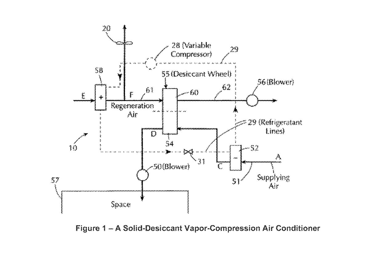
[0056]The invention claimed here and the benefits it provides can be appreciated by comparing its operation to that of the technology described in the Dinnage patent. FIG. 1 is a block diagram of a vapor-compression air conditioner as disclosed in the Dinnage patent. It shows a vapor-compression air conditioner in which a stream of supply air is cooled in a refrigerant evaporator (52) and a stream of regeneration air is heated in a refrigerant condenser (58). The cool, saturated supply air that leaves the refrigerant evaporator (52) is dried as it passes through the process sector (54) of a rotating desiccant wheel (55). The water absorbed by the desiccant is rejected to the regeneration air as the wheel rotates and what was the “process sector” becomes the “regeneration sector” (60) where the desiccant is heated by the regeneration air.

[0057]Although illustrated as applied to a vapor-compression air conditioner, the technology described in the Dinnage patent can increase the latent...


PUM


Abstract

A device for cooling and dehumidifying a first stream of air includes a first heat exchanger that cools the first stream of air from a first temperature to a lower second temperature, an absorber, a regenerator and one or more pumps and conduits. The device operates under conditions where liquid desiccant removes moisture from the first stream of air in the absorber and the second temperature of the first stream of air that leaves the first heat exchanger is lower than the temperature of the liquid desiccant supplied to the absorber.

Description

RELATED APPLICATION[0001]This application is a non-provisional based on U.S. Provisional Patent Application 61 / 895,809, entitled LIQUID-DESICCANT DIRECT-EXPANSION AIR CONDITIONER, filed Oct. 25, 2013, and U.S. Provisional Patent Application 62 / 015,155, entitled LIQUID-DESICCANT VAPOR-COMPRESSION AIR CONDITIONER, filed Jun. 20, 2014, the contents of which are incorporated herein in their entirety.GOVERNMENT INTEREST[0002]This invention was made with Government support under Grant No. SBIR FA8501-14-P-0005 awarded by the Department of Defense. The Government has certain rights in this invention.BACKGROUND[0003]Heat pumps are thermodynamic devices that can move thermal energy from a first temperature source to a second, higher temperature sink. This transfer of thermal energy in a direction opposite to the direction it passively flows (i.e., it passively flows from a higher temperature to a lower temperature) requires the expenditure of energy which can be supplied to the heat pump in ...

Claims


Application Information

Patent Timeline
IPC IPC(8): F24F3/14
CPCF24F3/1429F24F3/1417F24F2003/1458
Inventor LOWENSTEIN, ANDREW
Owner AIL RES
Features
  • Generate Ideas
  • Intellectual Property
  • Life Sciences
  • Materials
  • Tech Scout
  • Unparalleled Data Quality
  • Higher Quality Content
  • 60% Fewer Hallucinations
Learn More