Fuel gas circulation apparatus

a technology of fuel gas and circulation apparatus, which is applied in the direction of valve operating means/release devices, machines/engines, electrochemical generators, etc., can solve the problems of high disadvantageous production cost, difficult to produce fuel gas supply apparatus, and complicated structure of the casing, so as to reduce the generation of noise, reduce vibrations to the body or the diffuser, and reduce the effect of transmission

Active Publication Date: 2017-08-24
HONDA MOTOR CO LTD
View PDF2 Cites 3 Cited by
  • Summary
  • Abstract
  • Description
  • Claims
  • Application Information

AI Technical Summary

Benefits of technology

[0011]Thus, with the simple structure of providing the elastic member, vibrations generated by operation of the injector at the time of injecting the fuel gas can be absorbed suitably. Transmission of the vibrations to the body or the diffuser is reduced. Consequently, it is possible to reduce generation of noises, damages, etc. resulting from vibrations in the fuel gas circulation apparatus.

Problems solved by technology

In the above described fuel gas supply apparatus, since the diffuser is formed inside the casing, the casing has complicated structure.
It is difficult to produce the fuel gas supply apparatus, and the production cost is high disadvantageously.
Further, since the injector is fixed to the casing directly, the vibrations generated during operation of the injector are transmitted directly to the casing, and thus, the casing may be damaged, or noises may be generated as a result of the vibrations.

Method used


Image

  • Fuel gas circulation apparatus
  • Fuel gas circulation apparatus
  • Fuel gas circulation apparatus

Examples


Embodiment Construction

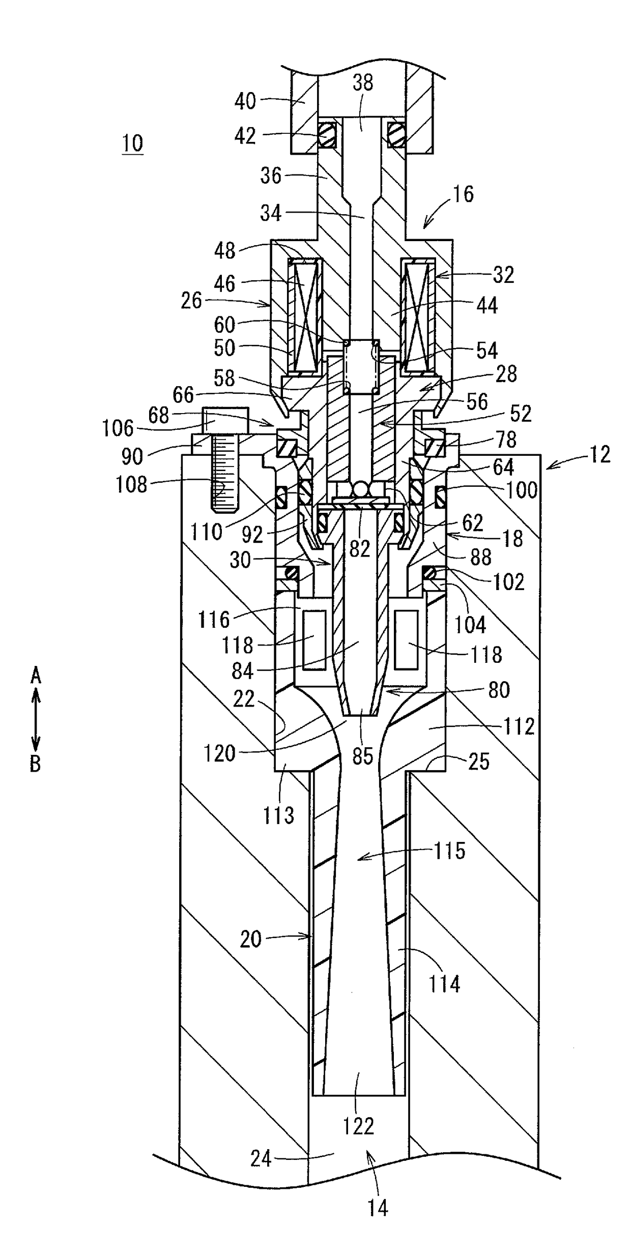
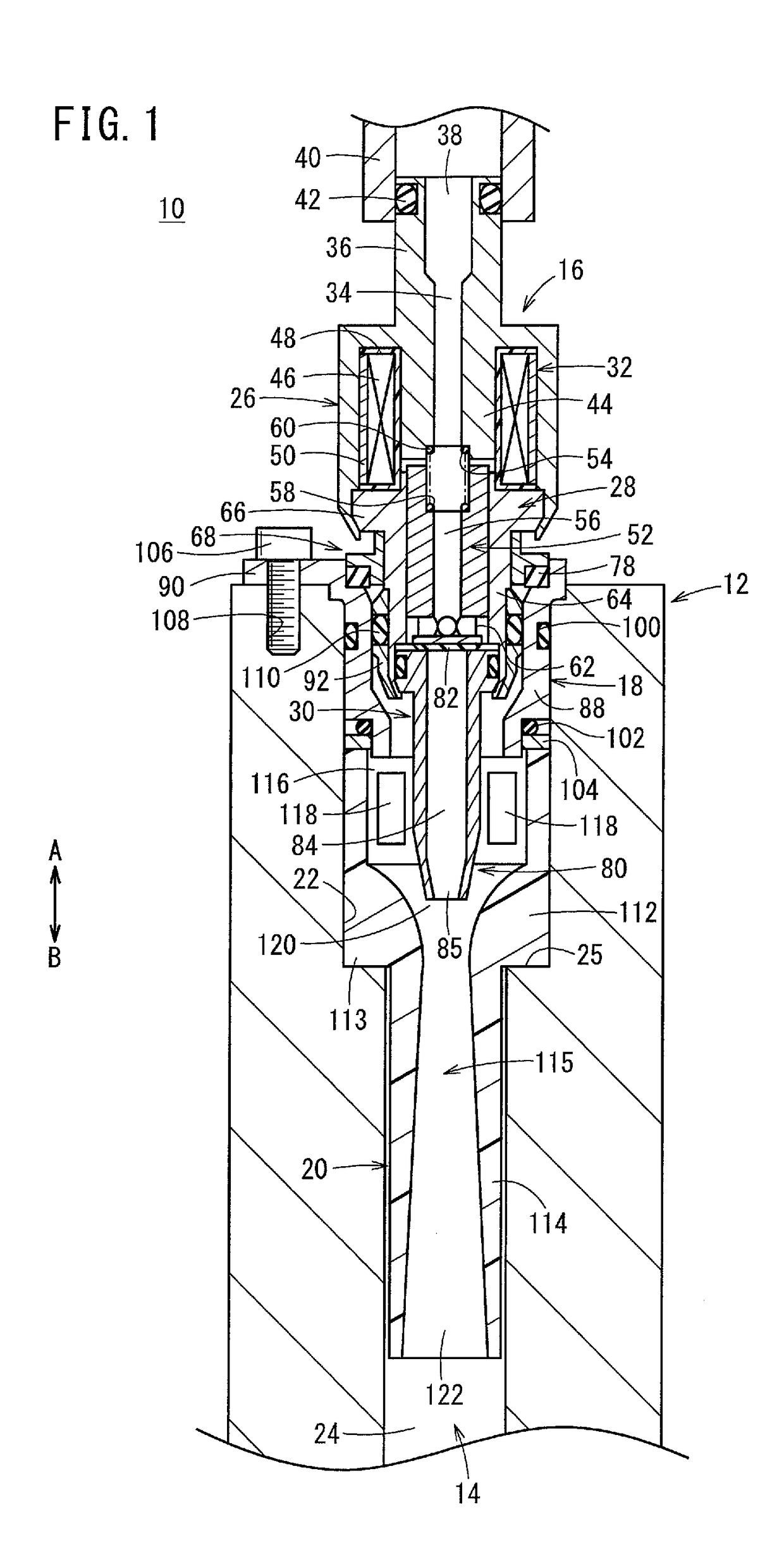
[0016]For example, a fuel gas circulation apparatus 10 is provided in a fuel cell system, between a fuel tank storing a fuel gas and a fuel cell stack. As shown in FIG. 1, the fuel gas circulation apparatus 10 includes an injector 16 provided at an attachment hole 14 of a body 12, for injecting the fuel gas, an attachment 18 for fixing the injector 16 to the body 12, and a diffuser 20 for mixing an off gas (fuel off gas) discharged from a fuel cell stack (not shown) with the fuel gas injected from the injector 16. The attachment hole 14 functions as a fuel gas supply channel to flow the fuel gas.

[0017]Hereinafter, a side of the fuel gas circulation apparatus 10 where the injector 16 is provided, indicated by an arrow A, will be referred to as the “proximal end side”, and a side of the fuel gas circulation apparatus 10 where the diffuser 20 is provided, indicated by an arrow B, will be referred to as the “distal end side”.

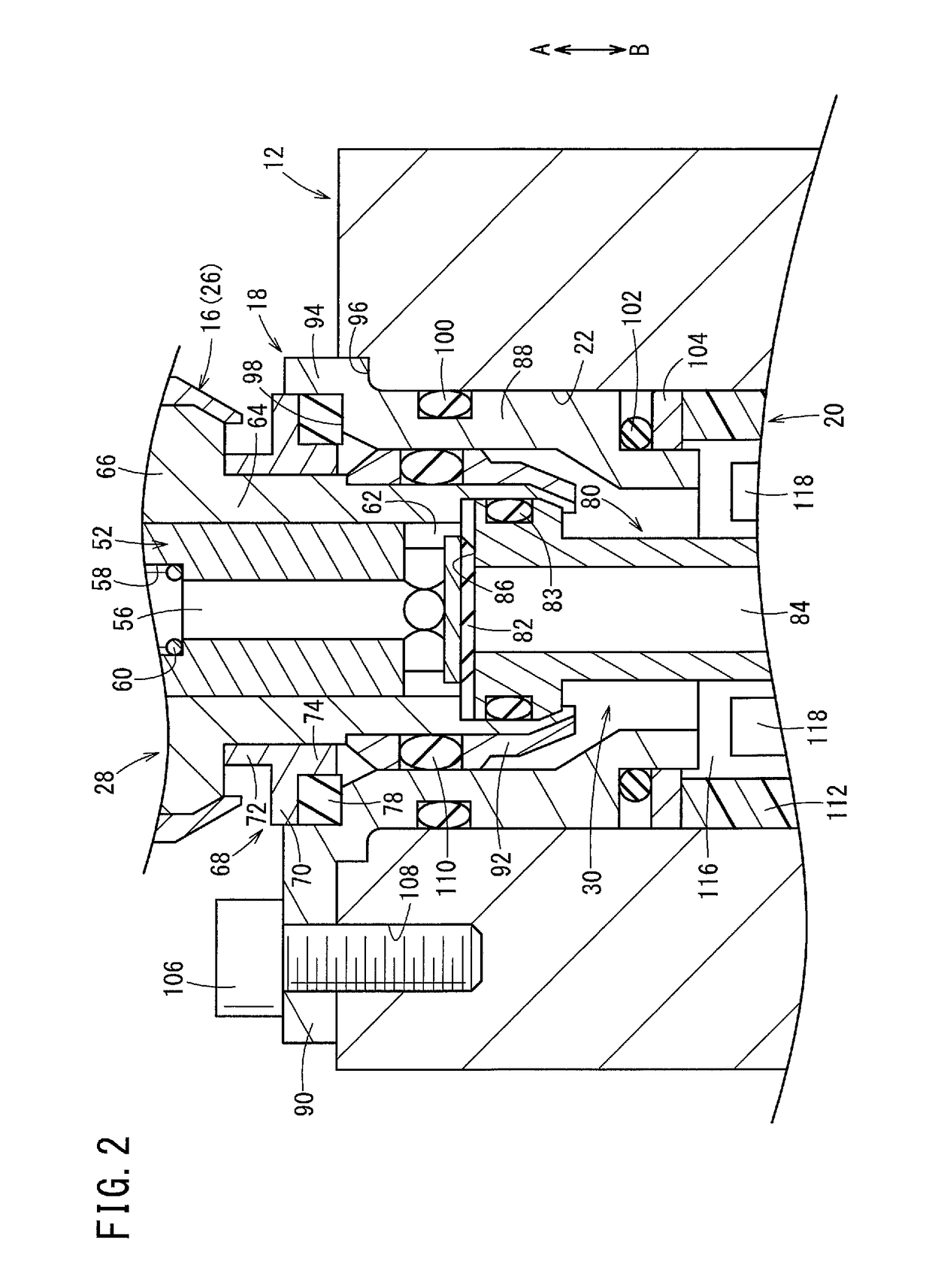
[0018]The attachment hole 14 includes a first hole 22 having a...


PUM

PropertyMeasurementUnit
outer circumferenceaaaaaaaaaa
pressureaaaaaaaaaa
elasticaaaaaaaaaa

Abstract

In a fuel gas circulation apparatus, a diffuser is accommodated in an attachment hole of a body. An injector is provided upstream of the diffuser through an attachment. A vibration absorption member made of elastic material is provided between a proximal end of a large diameter portion of this diffuser and a distal end of a main body in the attachment, and a ring member is provided adjacent to the vibration absorption member.

Description

CROSS-REFERENCE TO RELATED APPLICATION[0001]This application is based upon and claims the benefit of priority from Japanese Patent Application No. 2016-032655 filed on Feb. 24, 2016, the contents of which are incorporated herein by reference.BACKGROUND OF THE INVENTION[0002]Field of the Invention[0003]The present invention relates to a fuel gas circulation apparatus used in a fuel cell system, for circulating a redundant fuel off gas which has not been consumed in a fuel cell stack.[0004]Description of the Related Art[0005]Conventionally, in fuel cell systems, fuel gas supply apparatuses for supplying a fuel gas have been used. For example, in a fuel gas supply apparatus disclosed in Japanese Laid-Open Patent Publication No. 2008-196401, a diffuser is formed at one end of a casing, and an injector for injecting a fuel gas is provided at a position upstream of the diffuser. Further, a tapered nozzle is provided at the distal end of the injector. Further, by injecting the fuel gas fro...

Claims


Application Information

Patent Timeline
Patent Type & Authority Applications(United States)
IPC IPC(8): H01M8/04089H01M8/04746
CPCH01M8/04753H01M8/04097F04F5/16F04F5/463F04F5/48F16K31/0651F16K31/0686Y02E60/50F04F5/00F16K31/06
Inventor KOYAMA, TOMOYOSHIFUKUDA, TETSUYAINOUE, SATOSHI
Owner HONDA MOTOR CO LTD
Why Eureka
Try Eureka