Cable retainer assembly

a technology of retainer and cable, which is applied in the direction of flexible lead accommodation, coupling device connection, electrical apparatus, etc., can solve the problems of increasing manufacturing cost, and achieve the effect of improving structure or configuration, solidly and stably clamping

Inactive Publication Date: 2017-08-24
WANHO T MFG
View PDF0 Cites 3 Cited by
  • Summary
  • Abstract
  • Description
  • Claims
  • Application Information

AI Technical Summary

Benefits of technology

[0008]The primary objective of the present invention is to provide a cable retainer assembly including an improved structure or configuration for solidly and stably clamping and retaining the cable in position and for preventing the cable from being moved and disengaged or separated from the cable retainer assembly.

Problems solved by technology

However, the typical cable retainer assembly assemblies normally include a complicated structure or configuration that may not be easily and quickly made or manufactured and that may include a complicated making or manufacturing procedure and that may include a greatly increased manufacturing cost.

Method used


Image

  • Cable retainer assembly
  • Cable retainer assembly
  • Cable retainer assembly

Examples


Embodiment Construction

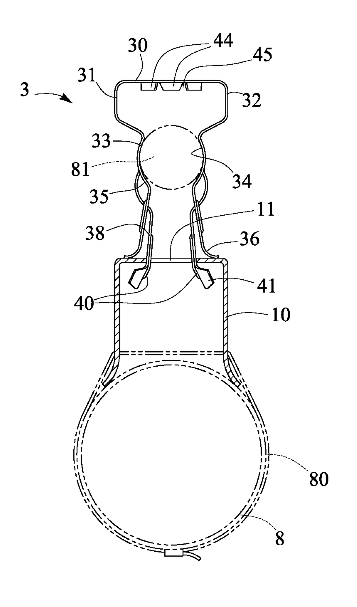
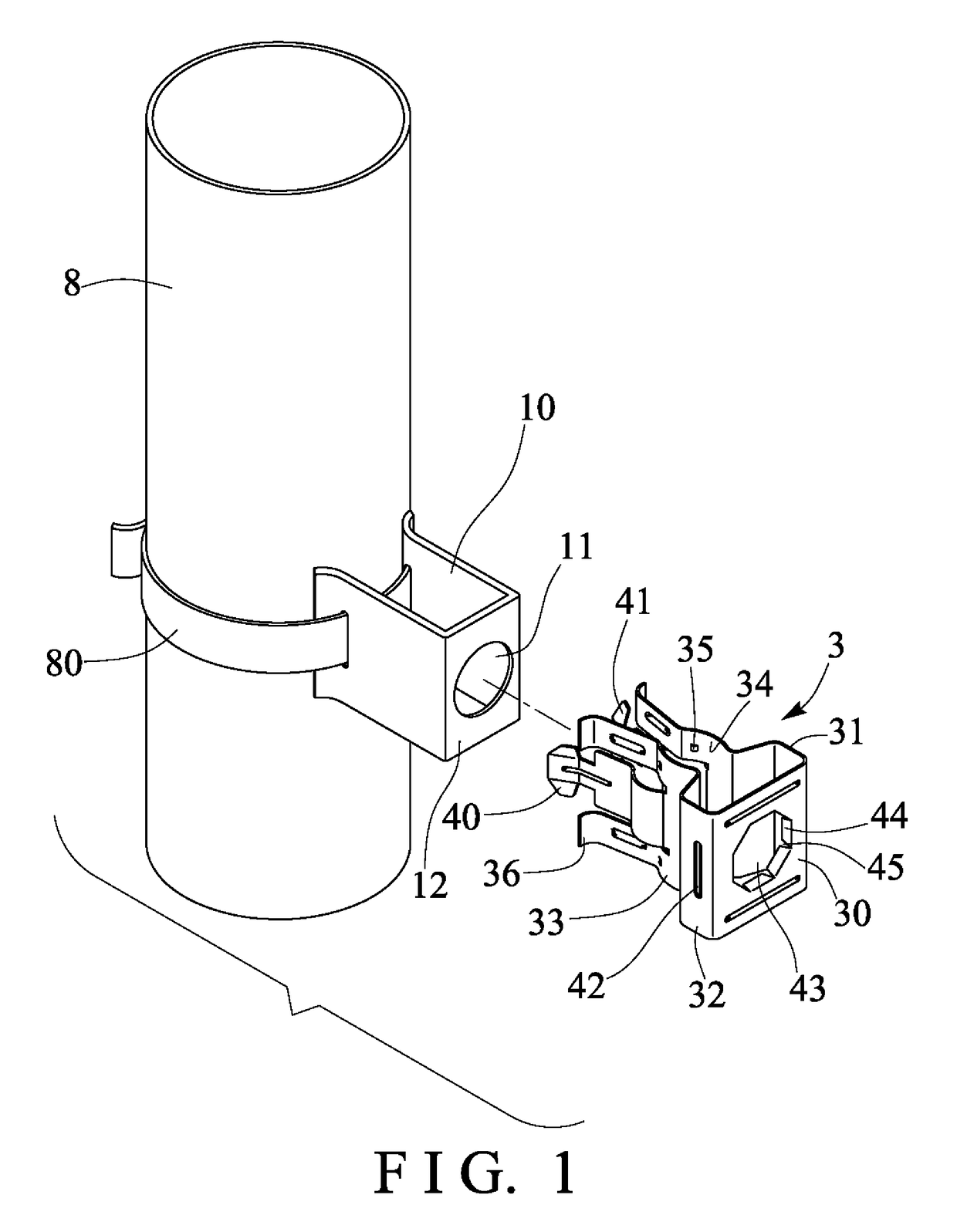
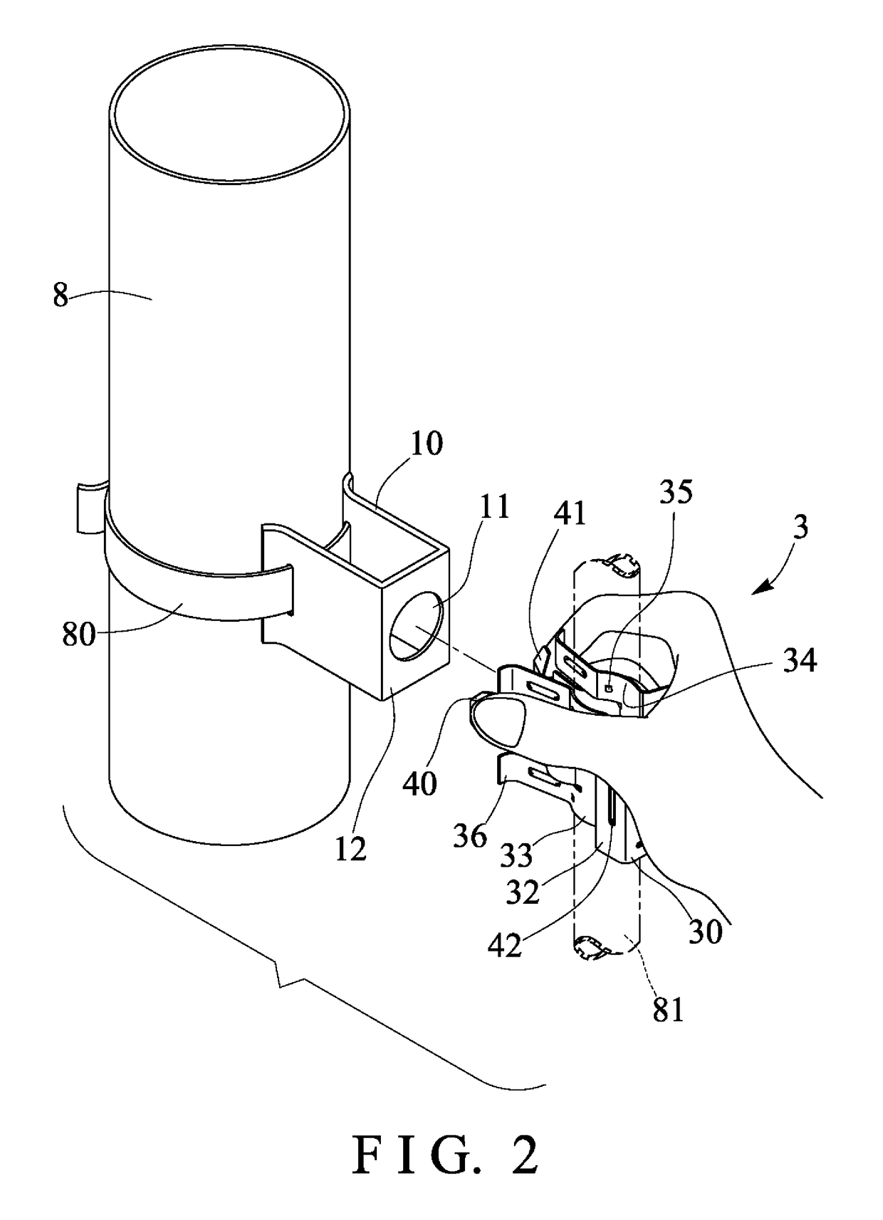
[0031]Referring to the drawings, and initially to FIGS. 1-6, a cable retainer assembly in accordance with the present invention comprises a base support device 10 including a bore or opening 11 formed therein, for example, the base support device 10 may include a spatial or three-dimensional or parallelepiped structure or configuration having the opening 11 formed in one of the surfaces 12 thereof, the base support device 10 may further be attached or mounted or secured or coupled to the other supporting members or facilities 8, such as a tubular member 8 with screws or bolts or catches or latches or fasteners or straps 80 or the like.

[0032]The cable retainer assembly further includes a clip device 3 also having a substantially spatial or three-dimensional or parallelepiped structure or configuration, the clip device 3 includes a front or base plate 30 and two side plates 31, 32 folded or extended from the base plate 30 and substantially perpendicular to the base plate 30 for formin...


PUM


Abstract

A cable retainer assembly includes a base support device having an opening, and a clip device having a base plate and two side plates folded from the base plate for clamping a cable between the side plates, the side plates each include one or more grooves for forming a flap in each of the side plates and for engaging the flaps of the side plates into the opening of the base support device, and for attaching the clip device to the base support device. The side plates of the clip device each include a curved portion directed toward each other for forming a chamber between the curved portions of the side plates and for engaging with the cable.

Description

BACKGROUND OF THE INVENTION[0001]1. Field of the Invention[0002]The present invention relates to a cable retainer assembly, and more particularly to a cable retainer assembly including an improved structure or configuration for solidly and stably clamping and retaining the cable in position and for preventing the cable from being moved and disengaged or separated from the cable retainer assembly.[0003]2. Description of the Prior Art[0004]Various kinds of typical cable retainer assembly assemblies have been developed and provided for clamping and retaining cables, such as electrical cables, optical cables etc. for signal transmitting purposes, and comprise two or more pieces or elements for clamping and retaining the cables in place.[0005]For example, U.S. Pat. No. 7,824,213 to Korcz et al., U.S. Pat. No. 8,413,416 to Egami, and U.S. Pat. No. 9,106,069 to Frizzell disclose several of the typical cable retainer assembly assemblies developed and provided for clamping and retaining cabl...

Claims


Application Information

Patent Timeline
Patent Type & Authority Applications(United States)
IPC IPC(8): H02G3/32H01R13/74
CPCH01R13/745H02G3/32H01R13/72
Inventor HSU, WAN CHANGELLIOTT, DAVID ROBERT
Owner WANHO T MFG
Why Eureka
Try Eureka