Stacked Pipe Light Emitting Diode Lighting Fixture

Inactive Publication Date: 2017-08-31
GELICA OPTICAL SYST CORP
View PDF0 Cites 2 Cited by
  • Summary
  • Abstract
  • Description
  • Claims
  • Application Information

AI Technical Summary

Benefits of technology

[0012]To achieve these and other advantages and in order to overcome the disadvantages of the conventional method in accordance with the purpose of the invention as embodied and broadly

Problems solved by technology

Without the ballast the fluorescent tube would rapidly be destroyed.
However, the ballast takes up physical space in the fluorescent light making the frame larger.
As a result, when two conventional fluorescent lights are positioned end to end there is a gap in the emitted light between the two lights.
This deficiency of light uniformity produces an inferior quality of emitted light.
The ballast used to slow down changes in the current by modula

Method used


Image

  • Stacked Pipe Light Emitting Diode Lighting Fixture
  • Stacked Pipe Light Emitting Diode Lighting Fixture
  • Stacked Pipe Light Emitting Diode Lighting Fixture

Examples


Example

[0043]Reference will now be made in detail to the preferred embodiments of the present invention, examples of which are illustrated in the accompanying drawings. Wherever possible, the same reference numbers are used in the drawings and the description to refer to the same or like parts.

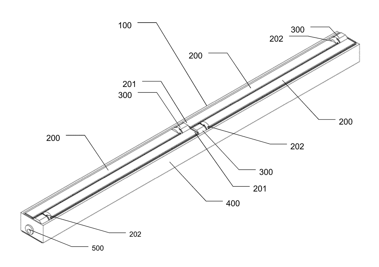
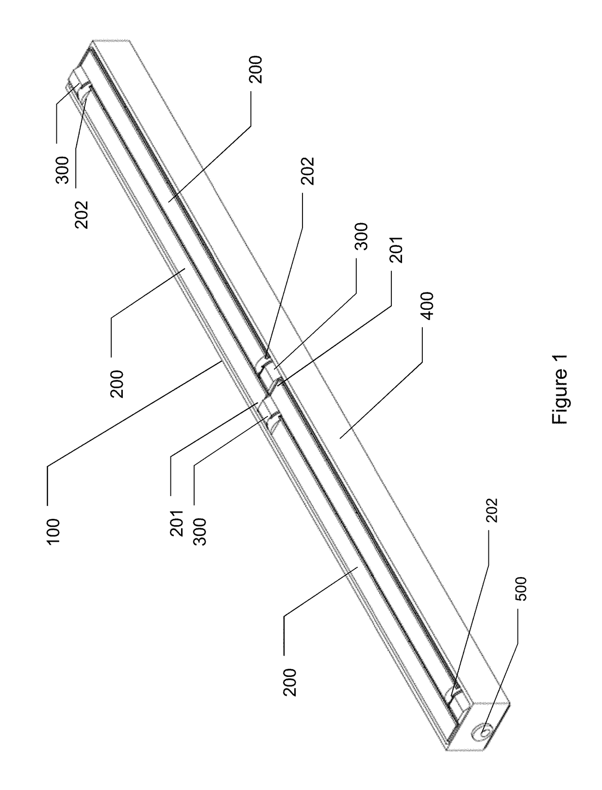
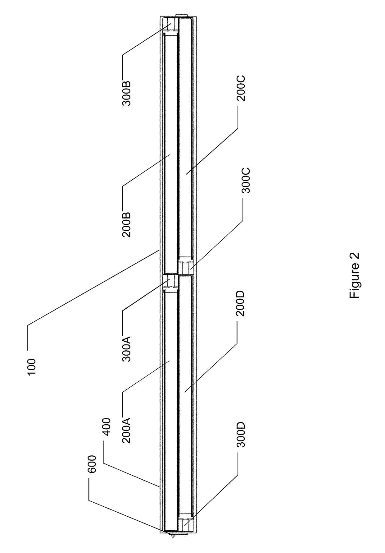
[0044]Refer to FIGS. 1-6, which are drawings illustrating a stacked pipe light emitting diode lighting fixture according to an embodiment of the present invention;

[0045]The stacked pipe light emitting diode (LED) lighting fixture 100 of the present invention comprises a housing 400, a plurality of light pipes 200, a plurality of LED modules 300, a power connector 500, and a power switch 600.

[0046]Each of the plurality of light pipes 200 comprises a light reflecting end 201 and a light receiving end 202. One LED module 300 is connected to the light receiving end 202 of each light pipe 200.

[0047]The power switch 600 is provided to turn the stacked pipe LED lighting fixture 100 on and off.

[0048]The powe...


PUM


Abstract

A stacked pipe light emitting diode lighting fixture with uniform and uninterrupted emitted light is disclosed. The stacked pipe light emitting diode lighting fixture comprises a plurality of transparent light pipes disposed in a housing. A light emitting diode module is connected to a light receiving end of each light pipe. The light pipes and connected light emitting diode modules are positioned so that light reflecting ends of the light pipes overlap the light emitting diode modules. As a result, the emitted light is uniform in intensity and uninterrupted for one end of the stacked pipe light emitting diode lighting fixture to the other end of the stacked pipe light emitting diode lighting fixture.

Description

BACKGROUND OF THE INVENTION[0001]Field of the Invention[0002]The present invention relates to lighting devices. More specifically, the present invention discloses a light emitting diode lighting fixture comprising a plurality of transparent light pipes in a stacked orientation to provide an uninterrupted linear light source with superior uniformity of emitted light.[0003]Description of the Prior Art[0004]Conventional fluorescent lights consist of one or two fluorescent tubes mounted in a frame. The sealed glass fluorescent tube contains a small amount of mercury and inert gas with a phosphor powder coating on the inside of the glass tube. When alternating current is applied to electrodes on both ends of the tube electrons migrate through the gas from one end of the tube to the other and the liquid mercury turns into a gas. Electrons in mercury atoms release light photons in the ultraviolet wavelength range which are not visible to humans so the phosphor coating is used to release ph...

Claims


Application Information

Patent Timeline
IPC IPC(8): F21K9/275F21V23/04F21K9/272F21V29/70F21V7/00F21V8/00F21V23/06
CPCF21K9/275G02B6/0096F21V23/04F21Y2115/10F21V29/70F21V7/00F21K9/272F21V23/06G02B6/0005F21K9/61F21V21/005
Inventor WU, WALTER DOWYEN, CHIH MINGCHEN, SHIH CHE
Owner GELICA OPTICAL SYST CORP
Why Eureka
Try Eureka