
Quench protection apparatus for superconducting magnet system

Active Publication Date: 2017-08-31
GENERAL ELECTRIC CO
View PDF1 Cites 2 Cited by
  • Summary
  • Abstract
  • Description
  • Claims
  • Application Information

AI Technical Summary

Benefits of technology

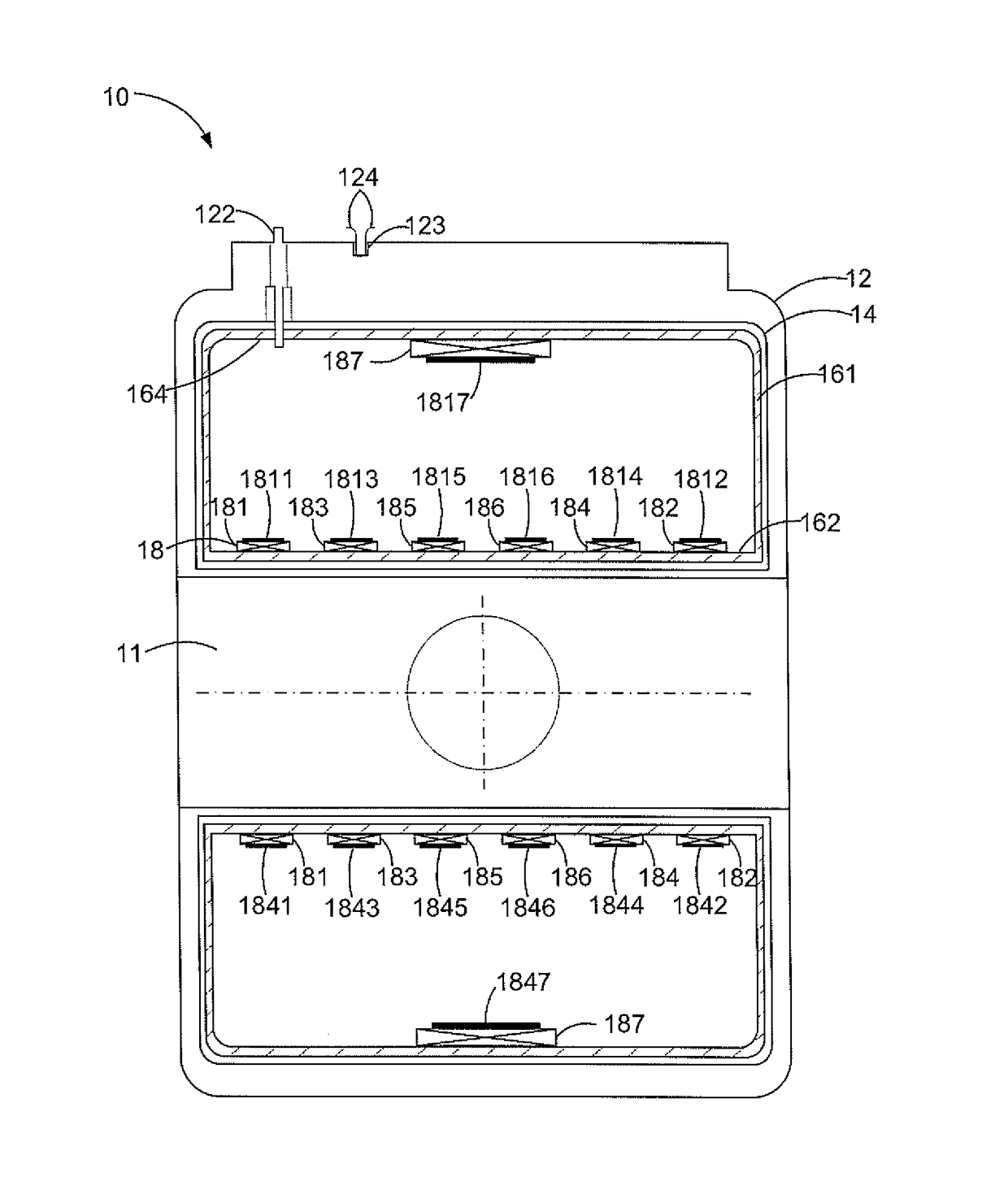
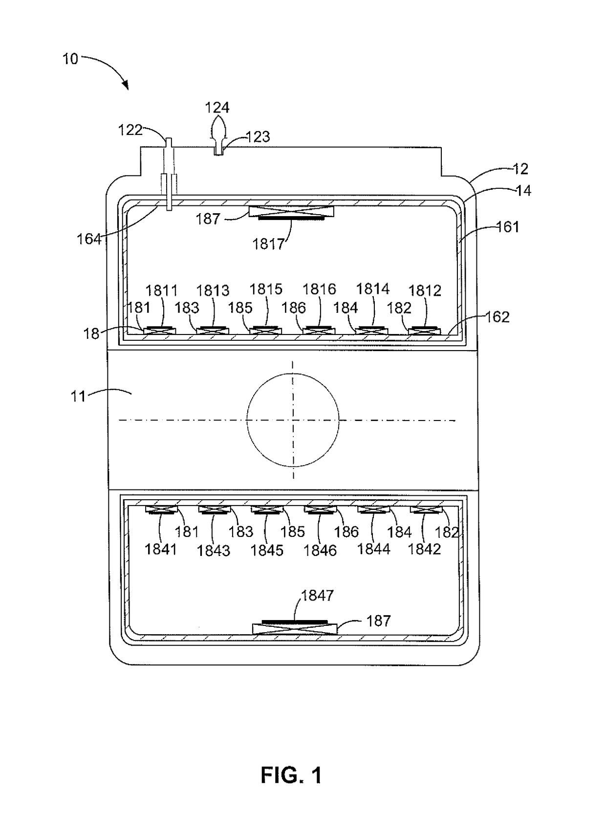
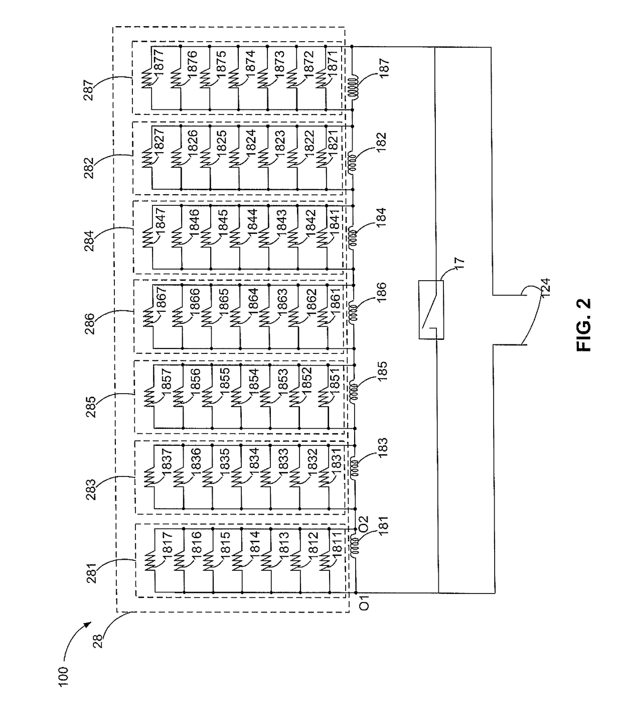
The patent text is discussing the need for a quench protection apparatus to protect superconducting coils from quenching (which is when a part of the coil region becomes resistive). The goal of the apparatus is to quickly disperse the stored energy of the superconducting magnet system throughout a larger mass, which reduces voltage and temperature peaks. This results in lower voltages and temperatures in the superconducting magnet compared to un-protected magnet quench.

Problems solved by technology

Superconducting magnets tend to be inherently unstable in that the temperature of a coil region of the magnet can rise relatively rapidly, due to a disturbance within the magnet itself or due to a cause external to the magnet.
When such coil region gets hot very rapidly the stored energy within the magnet tends to become dissipated rapidly into that finite resistive region and may severely damage the magnet, even in some cases causing an actual melting of the superconducting wires in the coil region.
This design criteria results in lower voltages and lower peak temperatures in superconducting magnet compared to un-protected magnet quench since the stored energy of the superconducting magnet system is dispersed throughout a larger mass.

Method used


Image

  • Quench protection apparatus for superconducting magnet system
  • Quench protection apparatus for superconducting magnet system
  • Quench protection apparatus for superconducting magnet system

Examples


Embodiment Construction

[0030]Unless defined otherwise, technical and scientific terms used herein have the same meaning as is commonly understood by one of those ordinarily skilled in the art to which this invention belongs. The terms “first”, “second”, and the like, as used herein do not denote any order, quantity, or importance, but rather are used to distinguish one element from another. Also, the terms “a” and “an” do not denote a limitation of quantity, but rather denote the presence of at least one of the referenced items, and terms such as “front”, “back”, “bottom”, and / or “top”, unless otherwise noted, are merely used for convenience of description, and are not limited to any one position or spatial orientation. Moreover, the terms “coupled” and “connected” are not intended to distinguish between a direct or indirect coupling / connection between two components. Rather, such components may be directly or indirectly coupled / connected unless otherwise indicated.

[0031]Unless indicated to the contrary, ...


PUM


Abstract

A quench protection apparatus includes a number N of superconducting coils and a heater matrix. The number N of superconducting coils are electrically coupled in series. The heater matrix module includes the number N of heater units. The number N of heater units is electrically coupled in parallel with the number N of superconducting coils respectively. A number M of the heater units each includes at least the number N of heaters. Each superconducting coil is thermally coupled with at least one heater of each of the number M of the heater units. The number of N-M of the heater units each includes at least one heater. Each of the number M of superconducting coils correspondingly coupled with the number M of the heater units is thermally coupled with at least one heater of each of the number N-M of the heater units. A superconducting magnet system protected by above quench protection apparatus is also provided.

Description

CROSS-REFERENCE TO RELATED APPLICATIONS[0001]This is a national stage application under 35 U.S.C. §371 (c) of PCT Patent Application No. PCT / US2015 / 054945, filed on Oct. 9, 2015, which claims priority to China Patent Application No. 201410554507.1, filed on Oct. 17, 2014, the disclosures of which are incorporated herein by reference in their entireties.BACKGROUND[0002]Embodiments of the invention relate generally to superconducting magnet systems, and in particular, to a quench protection apparatus which protects superconducting coil assemblage from damage during a quench.[0003]Superconducting magnet systems having relatively large energies are currently used in many applications. For example, superconducting magnet systems, storing energy of up to tens of mega Joules, are constructed for Magnetic Resonance Imaging (MRI) systems which are now being routinely used in large numbers in clinical environments for medical imaging. A part of such a MRI system is a superconducting magnet sy...

Claims


Application Information

Patent Timeline
IPC IPC(8): H01F6/02H01F6/04G01R33/3815H01F6/06
CPCH01F6/02G01R33/3815H01F6/04H01F6/06
Inventor XU, MINFENGLASKARIS, EVANGELOSSHEN, WEIJUNWANG, JIAN-SHEWU, ANBOBAI, YESONG, YUNXING
Owner GENERAL ELECTRIC CO
Learn More