
Moving Floor for Interactions with Virtual Reality Systems and Uses Thereof

Active Publication Date: 2017-09-07
VR MOVING FLOOR LLC
View PDF7 Cites 14 Cited by
  • Summary
  • Abstract
  • Description
  • Claims
  • Application Information

AI Technical Summary

Benefits of technology

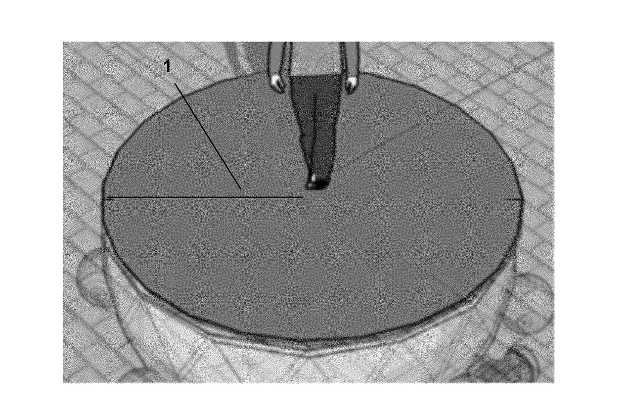
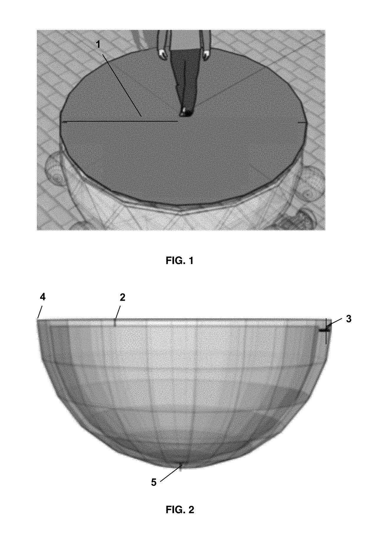
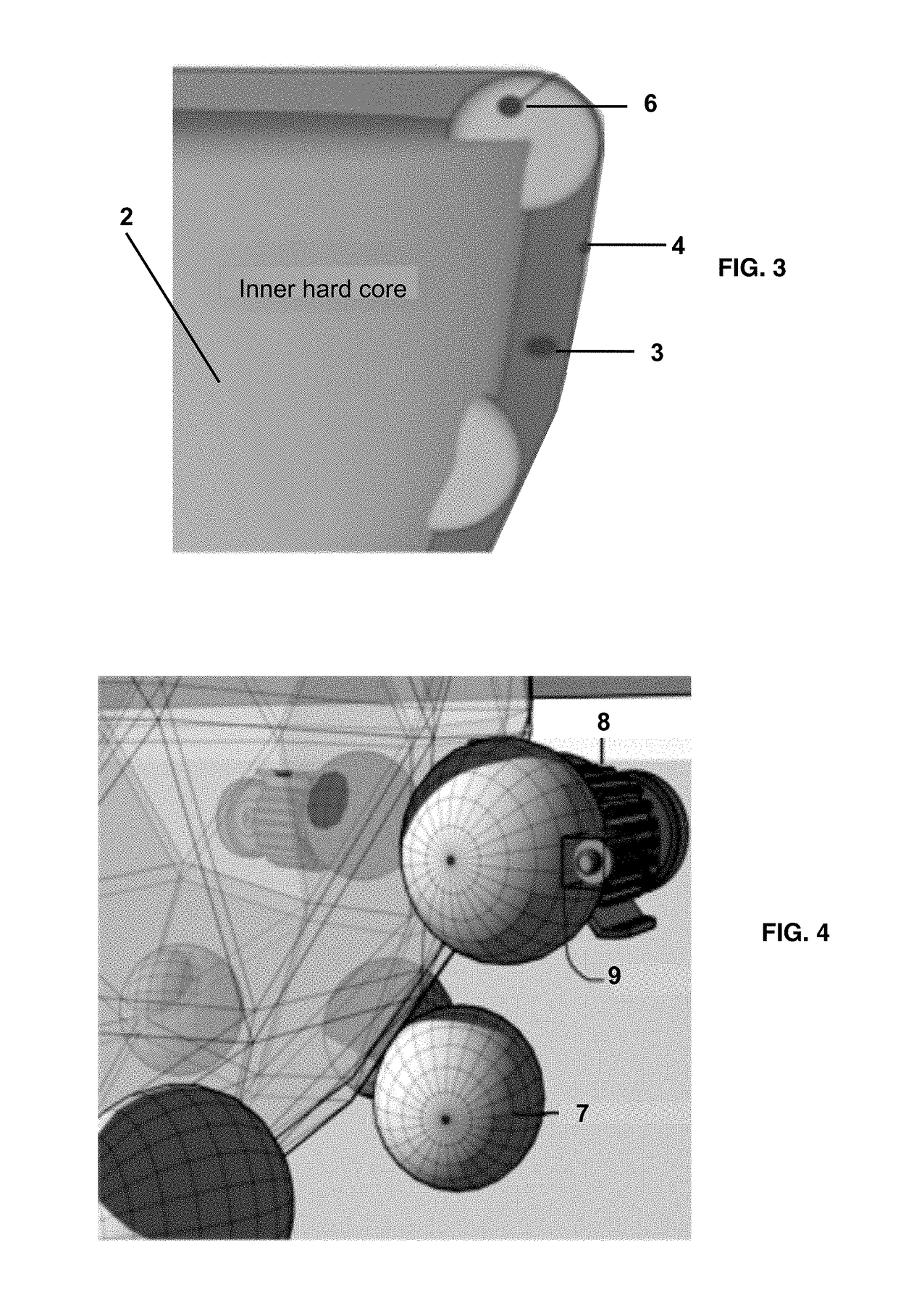
This patent describes a multi-functional moving floor device that interacts with virtual reality systems. The device has a flat top surface and is supported by a motorized control arms and sensors. It can be activated and deactivated and has a power module. The present invention also describes a user-interactive control device for interacting with virtual reality systems. This control device has an inner core, an outer flexible skin layer, and a plurality of control arms, weight sensors, hydraulic actuators, and a rotating base. The device can be customized for users and has a wall-like structure and a ring-like extension stage. The present invention also provides a method for interacting with a virtual reality system using the moving floor device. When a user applies a movement or series of movements to the device, signals are generated and transmitted to the virtual reality system and control spheres, and the device reacts accordingly. The technical effects of this invention include a multi-functional floor device that is easy to use and interact with virtual reality systems, as well as a user-interactive control device that allows for more intuitive interactions with virtual objects.

Problems solved by technology

However, the accuracy of this system is very limited, especially for the depth of the motion (distance between the pointing device and the beacon) as all the calculation and estimation of the motions are based on camera captured images.
It would be difficult using this system to accurately simulate the distance and velocity of running, crawling, walking, etc.
Moreover, the range of the motion (i.e., running or walking distance) for this system is limited to the range of the camera and the dimension of the room where the game console is placed, making it impossible to interact with virtual reality environments that involve long distance running, walking or crawling.
However, the KINECT system did not eliminate the motion range limitation enforced by the coverage range of the camera or the dimension of the room.
It did not provide any solution to simulate long distance running, walking or crawling.
However, none of the control / interaction systems discussed above are able to fully take advantage of the walking, running, jumping, and other fluid movement interaction with virtual reality environment.
VIRTUIX (Houston, Tex.) has recently developed one of the first “moving floor”, called the VIRTUIX OMNI but the design of VIRTUIX is hindered in several ways.
Overall, the user experience of VIRTUIX OMNI could be fairly uncomfortable and far from natural walking experience due to special shoes, a “sensor / restraining waistband”, and a bowl-shaped walking area.
Particularly, the prior art is deficient in these aspects.

Method used


Image

  • Moving Floor for Interactions with Virtual Reality Systems and Uses Thereof
  • Moving Floor for Interactions with Virtual Reality Systems and Uses Thereof
  • Moving Floor for Interactions with Virtual Reality Systems and Uses Thereof

Examples


example 1

Memory Playback With 360° Camera

[0121]During the wedding ceremony, the bride wears a gyro-stabilized micro-camera that is embedded on top of her wedding veil to film the scene in 360 degrees. After the wedding, the video is uploaded to a computer. She then goes to the moving floor device and walk the exact same path repeatedly, essentially re-experiencing her wedding. During the re-experiencing process, she can proceed forward or go backward in time in the virtual environment. As she walks down the isle toward the minister she sees time moving forward. If she walks backward in the wedding isle, time reverses in the virtual reality (i.e. the 360° video). The viewer is able to observe the scenes in any direction due to the 360° filming. Other people may might also watch and experience the wedding playback using the moving floor device.

example 2

[0122]Integration with GOOGLE STREETVIEW and GOOGLE EARTH

[0123]A user is looking for an apartment. He hops on the moving floor device, puts his glasses on, and enables GOOGLE STREETVIEW mode. He instructs the system to put him at the address of his proposed apartment. He then takes a walk around the vicinity to see if he likes the community.

[0124]A student in world geography class uses the moving floor device coupled with a pair of virtual reality glasses to explore the world in GOOGLE EARTH. He is able to set her height at 1 mile and walks the globe in the view of a giant. When reaches the destination, he can reduce his virtual height to normal and walk around.

example 3

Sharing the Experience Via Social Network Using a Virtual Reality Device

[0125]A user shares his vacation in the Amazon on a social network in 360° high-resolution video. The shared link provided allows others to go on the same path and see the Amazon by themselves. They do not necessarily see the same things as the user who shot the video, since they can look in completely different directions from other users.


PUM


Abstract

Provided herein is a multi-functional moving floor device for interacting with virtual environments. Generally, the moving floor device has a substantially hemispherical body with a flat top surface and an inner core, a control module, an action module, a wall module, a computing unit communicably connected with the control module, the action module, the wall module and a virtual reality system with means to activate and deactivate the device and a power module. The moving floor devices may comprise wall-like structures and may simulate virtual walls. Also provided is a user-customized method for interacting with virtual reality via the multi-functional moving floor device.

Description

CROSS-REFERENCE TO RELATED APPLICATIONS[0001]This application is a continuation under 35 U.S.C. of pending international application PCT / US2015 / 061789, filed Nov. 20, 2015, which claims benefit of priority under 35 U.S.C. §119(e) of provisional application U.S. Ser. No. 62 / 157,099, filed May 5, 2015, now abandoned, of provisional application U.S. Ser. No. 62 / 157,090, filed May 5, 2015, now abandoned, of provisional application U.S. Ser. No. 62 / 157,075, filed May 5, 2015, now abandoned, and of provisional application U.S. Ser. No. 62 / 082,967, filed Nov. 21, 2014, now abandoned, the entirety of all of which are hereby incorporated by reference.BACKGROUND OF THE INVENTION[0002]Field of the Invention[0003]The present invention relates generally to the field of interactions with virtual reality systems. More specifically, the present invention relates to a moving floor device and system thereof for users to interact with virtual reality environments and systems using user-applied movemen...

Claims


Application Information

Patent Timeline
IPC IPC(8): A63F13/214A63F13/98A63F13/285
CPCA63F13/214A63F2300/8082A63F13/98A63F13/285A63F13/24A63F13/45A63F13/50A63F13/90G06F3/011G06F3/016G06F3/017G06F3/0354G06F2203/012G09B9/00
Inventor MATINA, NICHOLAS A.
Owner VR MOVING FLOOR LLC
Learn More