
Polishing apparatus

a technology of polishing apparatus and polishing pad, which is applied in the direction of manufacturing tools, lapping machines, and abrasive surface conditioning devices. it can solve the problems of low operating rate of the cmp apparatus, the number of substrates polished does not necessarily reflect the accurate end point of the polishing pad life, and the polishing pad performance decreases. , the effect of accurately determined and decreased polishing performan

Inactive Publication Date: 2017-09-07
EBARA CORP
View PDF10 Cites 1 Cited by
  • Summary
  • Abstract
  • Description
  • Claims
  • Application Information

AI Technical Summary

Benefits of technology

The present invention aims to provide a polishing apparatus that can accurately determine the life end of its polishing pad and reduce the frequency of replacing it. It does this by analyzing the condition of the polishing pad based on the amount of wear and changes in motor current for rotating the polishing table and the top ring. Similarly, the dresser used in the polishing process can also be diagnosed based on the cut rate and motor current analysis, ensuring accurate determination of its lifespan. This helps improve the efficiency and cost-effectiveness of the polishing process.

Problems solved by technology

Since the worn polishing pad cannot exhibit its intended polishing performance, it is necessary to replace the polishing pad regularly.
However, the number of substrates polished does not necessarily reflect an accurate end point of the life of the polishing pad.
Moreover, such frequent replacement of the polishing pad would result in a low operating rate of the CMP apparatus.
As a result, it has been difficult to accurately determine the end point of the life of the polishing pad from the surface position of the polishing pad.
The lowered dressing performance can lower the polishing performance of the polishing pad.

Method used


Image

  • Polishing apparatus
  • Polishing apparatus
  • Polishing apparatus

Examples


Embodiment Construction

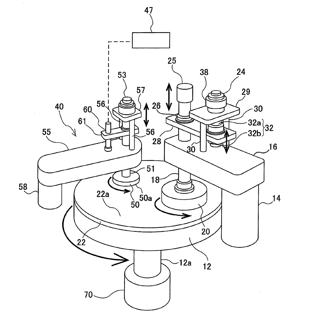
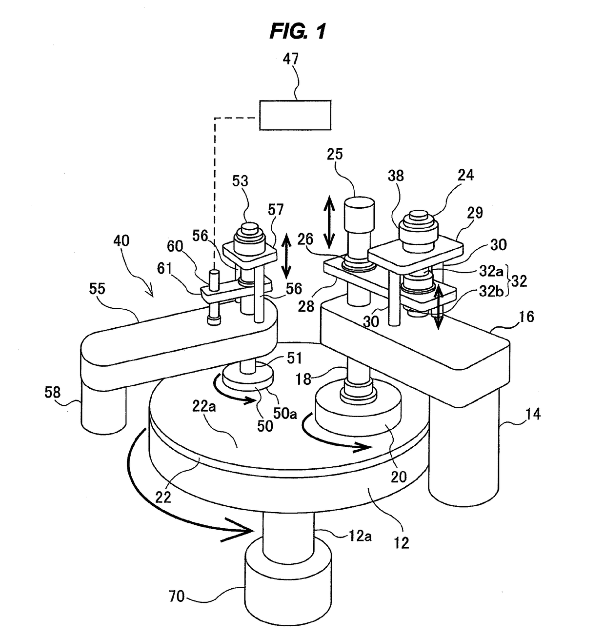
[0038]FIG. 1 is a schematic view of a polishing apparatus according to an embodiment of the present invention. As shown in FIG. 1, the polishing apparatus has a polishing table 12, a top ring swing arm 16 coupled to an upper end of a support shaft 14, a top ring shaft 18 supported by a free end of the top ring swing arm 16, a top ring 20 having approximately a disk shape and coupled to a lower end of the top ring shaft 18, and a diagnostic device 47 for processing various kinds of data. Although not shown, the diagnostic device 47 has a storage device for storing the data therein and an arithmetic processor for processing the data. Although not shown in FIG. 1, the top ring shaft 18 is coupled to a top ring rotating motor via a coupling mechanism, such as a timing belt, so that the top ring shaft 18 is rotated by the motor. This rotation of the top ring shaft 18 causes the top ring 20 to rotate about the top ring shaft 18 in a direction indicated by arrow.

[0039]The polishing table 1...


PUM


Abstract

A polishing apparatus includes a table rotating motor configured to rotate a polishing table about its own axis, a top ring rotating motor configured to rotate a top ring about its own axis, a dresser configured to dress a polishing pad, and a pad-height measuring device configured to measure a height of the polishing pad. The polishing apparatus also includes a diagnostic device configured to calculate an amount of wear of the polishing pad from the height of the polishing pad and to determine the end of a life of the polishing pad based on the amount of the wear of the polishing pad, the torque or current of the table rotating motor, and the torque or current of the top ring rotating motor.

Description

BACKGROUND OF THE INVENTION[0001]Field of the Invention[0002]The present invention relates to a polishing apparatus for polishing a substrate, such as a wafer, and more particularly to a polishing apparatus having a function to diagnose a condition of a polishing pad or a dresser to determine the end of its life.[0003]Description of the Related Art[0004]In fabrication of semiconductor devices, planarizing a surface of a substrate is a very important process. A typically used technique for the surface planarization is chemical mechanical polishing (CMP). In this chemical mechanical polishing, the surface of the substrate is polished by bringing the substrate into sliding contact with a polishing surface of a polishing pad, while supplying a polishing liquid that contains abrasive grains, e.g., silica (SiO2), onto the polishing surface. This chemical mechanical polishing is conducted using a CMP apparatus. This[0005]CMP apparatus has a polishing table for supporting the polishing pad ...

Claims


Application Information

Patent Timeline
Patent Type & Authority Applications(United States)
IPC IPC(8): B24B37/005B24B49/16B24B37/10B24B49/18
CPCB24B37/005B24B37/107B24B49/16B24B49/18B24B37/04B24B53/017H01L21/304
Inventor WATANABE, KATSUHIDEIHARA, MASAKAZU
Owner EBARA CORP
Learn More