

Liquid crystal display panel and method of forming the same
a technology of liquid crystal display and display panel, which is applied in the field of lcd panels, can solve the problems of low qr alignment efficiency, complicated production process, and current display appliances that only show a limited variety of colors, and achieve the effect of reducing production costs and enhancing the transmittance of polarizers and color gamut of lcd panels
- Summary
- Abstract
- Description
- Claims
- Application Information
AI Technical Summary
Benefits of technology
Problems solved by technology
Method used
Image

Examples
first embodiment
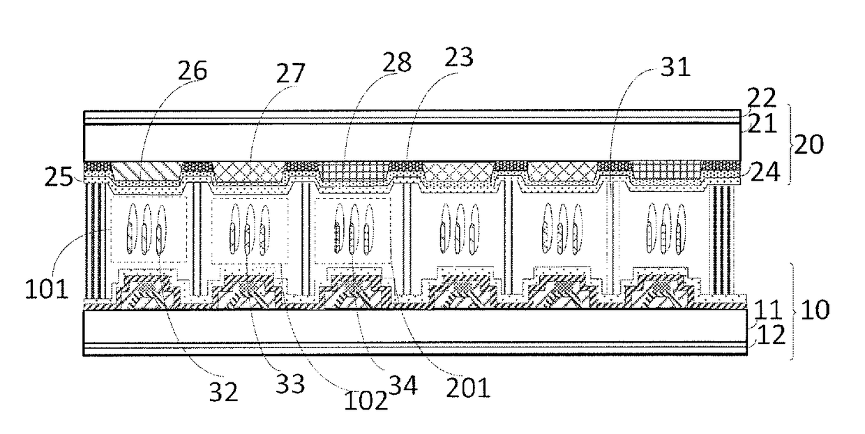
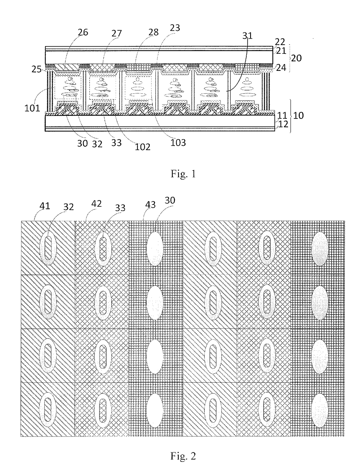
[0041]Please refer to FIG. 1. FIG. 1 is a structure diagram of a LCD panel of the present invention.
[0042]The LCD panel of the present invention comprises a first substrate 20, a second substrate 10, and a liquid crystal layer, disposed between the first substrate 20 and the second substrate 10. The first substrate 20, e.g. is a color film substrate, and the second substrate 10, e.g. is an array substrate. The first substrate 20 comprises a first base substrate 21, and a first polarizer 22 disposed on an external side of the first substrate. A color resist layer can further be disposed on the first base substrate. The color resist layer comprises a red color film 26, green color film 27 and blue color film 28. A black matrix 23 can be disposed between two adjacent color films. An insulation layer 24 and a transparent conducting layer 25 are installed on the color resist layer.
[0043]An isolation layer is disposed on the transparent conducting layer 25. The isolation layer comprises a...
second embodiment
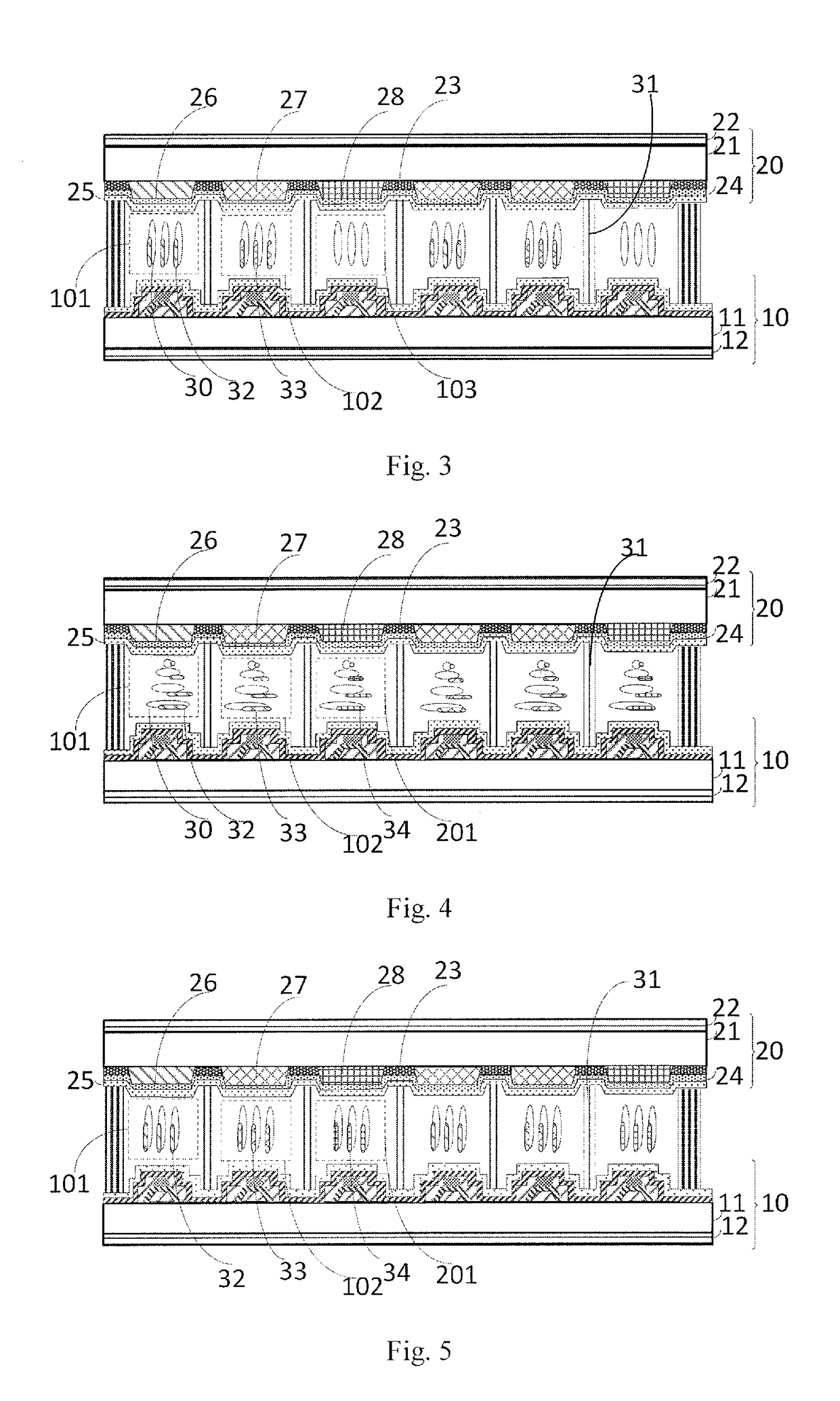
[0060]Please refer to FIG. 4. FIG. 4 is a structure diagram of a LCD panel of the present invention.
[0061]The LCD panel of the present invention comprises a first substrate 20, a second substrate 10, and a liquid crystal layer, disposed between the first substrate 20 and the second substrate 10. The first substrate 20, e.g. is a color film substrate, and the second substrate 10, e.g. is an array substrate. The first substrate 20 comprises a first base substrate 21, and a first polarizer 22 disposed on an external side of the first substrate. A color resist layer can further be disposed on the first base substrate. The color resist layer comprises a red color film 26, green color film 27 and blue color film 28. A black matrix 23 can be disposed between two adjacent color films. An insulation layer 24 and a transparent conducting layer 25 are installed on the color resist layer.
[0062]An isolation layer is disposed on the transparent conducting layer 25. The isolation layer comprises a...
PUM
| Property | Measurement | Unit |
|---|---|---|
| colors | aaaaa | aaaaa |
| brightness | aaaaa | aaaaa |
| color | aaaaa | aaaaa |
Abstract
Description
Claims
Application Information