Control system for elongate instrument

a technology of control system and elongate instrument, which is applied in the field of control system of elongate instrument, can solve the problems of obstructing the opening of a branch vessel, reducing the predictability and responsiveness of an instrument, and previously implanted devices may also pose challenges, so as to improve the control of tortuous patient anatomy, reduce manufacturing costs, and control the effect of elongate instrument quickly and precisely

Inactive Publication Date: 2017-09-14
BLATT ERIC D
View PDF3 Cites 33 Cited by
  • Summary
  • Abstract
  • Description
  • Claims
  • Application Information

AI Technical Summary

Benefits of technology

[0019]An advantage of the invention is that it provides an intuitive interface that allows a physician to rapidly and precisely control an elongate instrument.
[0020]Another advantage of the invention is that it provides an elongate instrument that does not need to be torqued for steering, thereby allowing improved control in tortuous patient anatomy and reduced manufacturing expense.
[0021]A further advantage of the invention is that it provides a control tool that may incorporate haptic feedback to allow a physician to feel or observe contact forces applied at a distal tip of an elongate instrument.
[0022]A further advantage of the invention is that it provides an elongate instrument in which the distal tip can be shaped into a desired configuration, thereby allowing the physic

Problems solved by technology

For example, blood vessels or other body lumens may be tortuous which may reduce the predictability and responsiveness of an instrument that is advanced through the tortuous anatomy.
Previously implanted devices may also pose challenges.
For example, a previously installed stent or graft may obstruct the opening to a branch vessel.
This does not allow the physician to freely control the position of the distal tip of the tool, nor does it allow the physi

Method used


Image

  • Control system for elongate instrument
  • Control system for elongate instrument
  • Control system for elongate instrument

Examples


Embodiment Construction

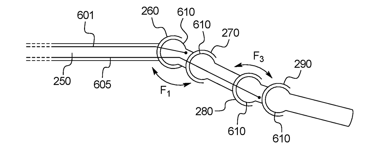
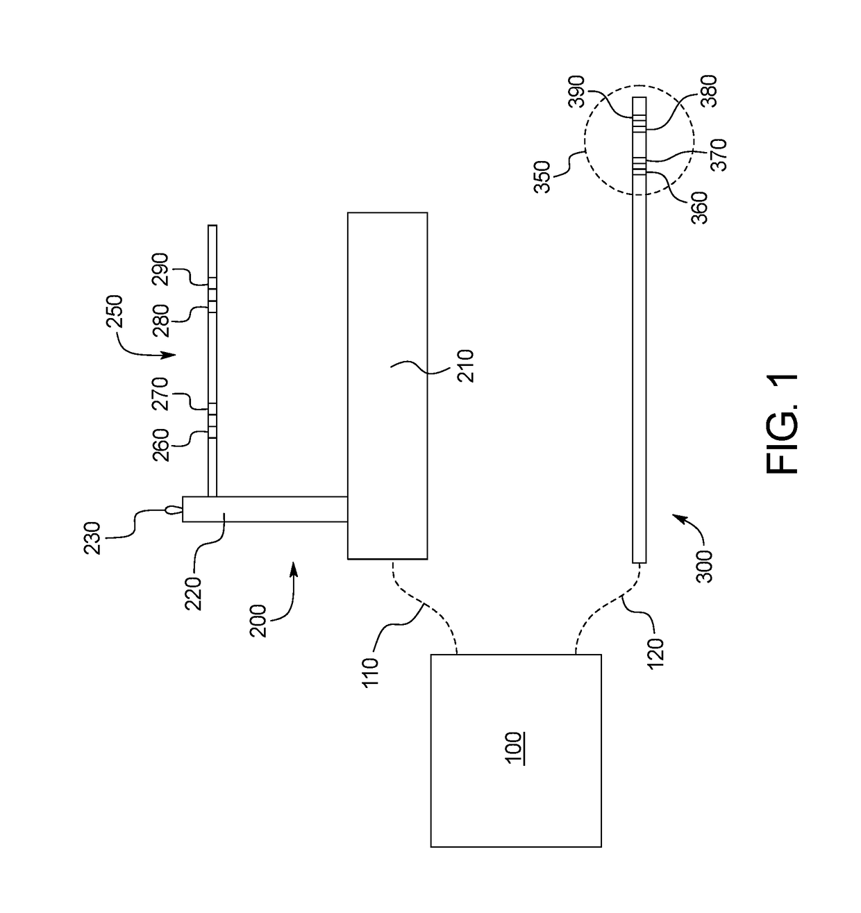
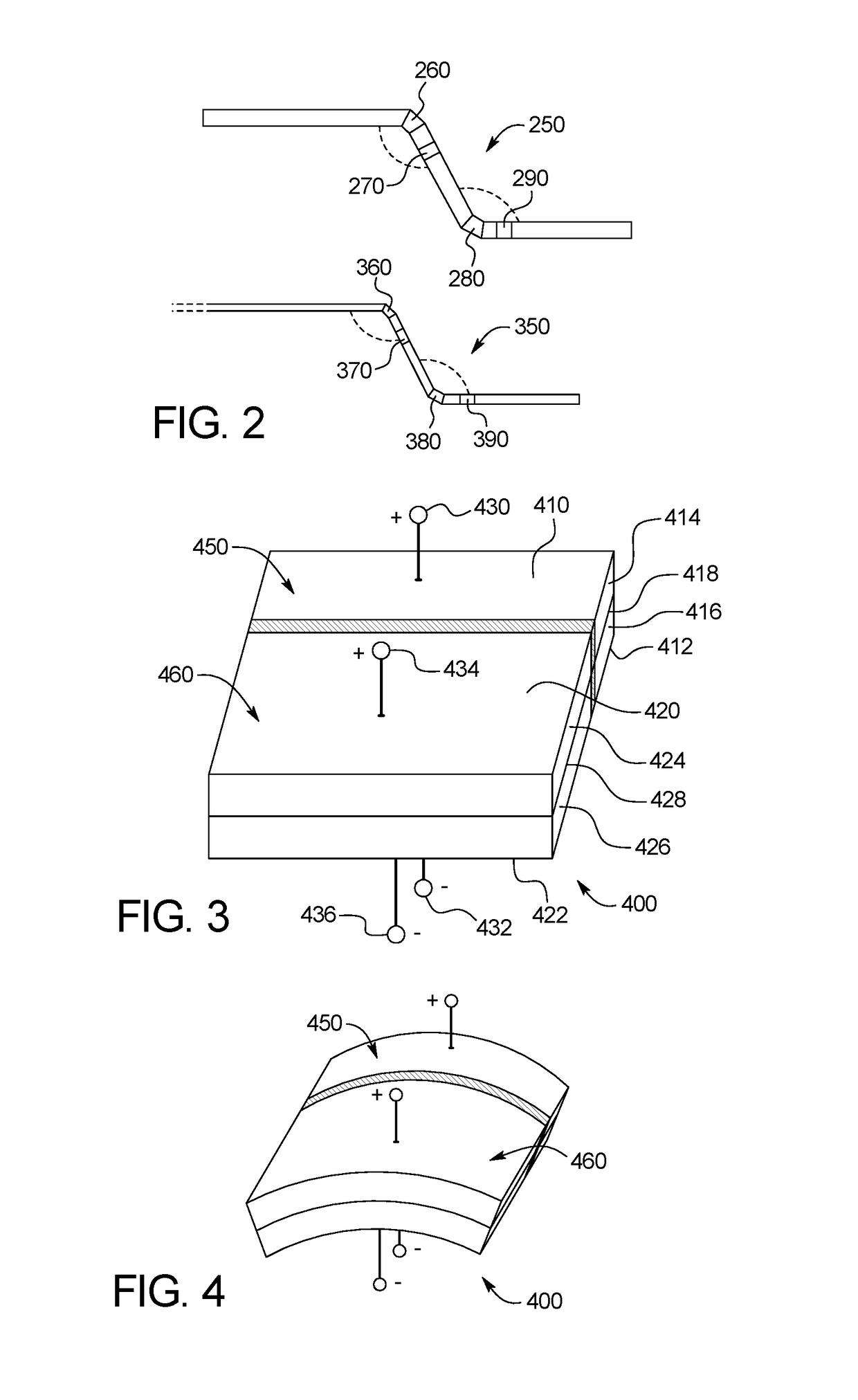
[0049]FIG. 1 shows an example of a control system including a control tool 200, a processor unit 100, and an elongate member 300. The control tool 200 may include a base 210, a housing 22, and a joystick 250. The joystick 250 may include one or more bending segments. In this embodiment, the joystick is shown having four bending segments 260, 270, 280, 290. The control tool may further include a locking switch 230. While the switch 230 is illustrated as a toggle switch, it may alternately be configured a button or any other switching means. The locking switch 230 may be used to toggle the control tool between a first configuration in which one or more of the bending segments may be freely bent and a second configuration in which they are locked in a selected position.

[0050]An elongate member 200 may be a guidewire, catheter, sheath, laparoscopic instrument, or other medical device. For purposes of illustration, the elongate member 200 is depicted as a guidewire 200, but the principle...


PUM


Abstract

A system for performing minimally invasive surgery includes a control tool and an elongate member for insertion into a body lumen. The control tool includes a first control tool bending segment and a first control tool transducer configured to generate a first control tool deflection signal based on manipulation of the first control tool bending segment. The elongate member includes a first elongate member bending segment at a distal portion and a first elongate member actuator configured to apply a force at the first elongate member bending segment. The system further includes a processor unit in communication with the control tool and the elongate member. Upon receipt of the deflection signal, the processor generates a first elongate member actuator signal configured to cause the first elongate member bending segment to move in accordance with the deflection signal.

Description

CROSS-REFERENCE TO RELATED APPLICATIONS[0001]This application incorporates by reference and claims the benefit of priority to U.S. Provisional Application No. 62 / 305,171, filed on Mar. 8, 2016.BACKGROUND OF THE INVENTION[0002]The present subject matter relates generally to methods and apparatuses for selectively manipulating an elongate instrument. More specifically, the present invention relates to methods and apparatuses for providing enhanced control of elongate medical tools including but not limited to guidewires, sheaths, catheters, endoscopes, laporoscopic tools, etc.[0003]Minimally invasive surgical procedures have become increasingly common due to their potential to reduce complications and discomfort while accelerating recovery time. These procedures typically involve inserting an elongate device into an opening in the body. In the case of laporoscopic surgery, the physician creates an opening to directly access a tissue region, and then inserts one or more flexible or rig...

Claims


Application Information

Patent Timeline
IPC IPC(8): A61B34/00A61B17/00A61M25/01
CPCA61B34/71A61B34/76A61M2205/50A61B17/00234A61M25/0105A61B2017/00314A61B2017/00323
Inventor BLATT, ERIC D.
Owner BLATT ERIC D
Why Eureka
Try Eureka