
Tire pressure estimation apparatus and estimation method thereof

a tire pressure estimation and tire technology, applied in tire measurement, vehicle components, transportation and packaging, etc., to achieve accurate and efficient estimation of tire pressure sta

Active Publication Date: 2017-09-14
HL MANDO CORP
View PDF0 Cites 0 Cited by
  • Summary
  • Abstract
  • Description
  • Claims
  • Application Information

AI Technical Summary

Benefits of technology

The present invention provides a device and a method for accurately and efficiently estimating the pressure of a tire, while inducing a driver to drive with care and rapidly responding to changes in the tire state. This helps to suppress anxiety about the current tire state and ensures safe driving.

Problems solved by technology

Since the conventional tire pressure estimating apparatus has a limitation in accurately and efficiently estimating the pressure state of the tire, an initial response to the current tire state is delayed, thereby causing a traffic accident.

Method used


Image

  • Tire pressure estimation apparatus and estimation method thereof
  • Tire pressure estimation apparatus and estimation method thereof
  • Tire pressure estimation apparatus and estimation method thereof

Examples


first embodiment

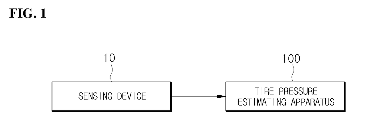
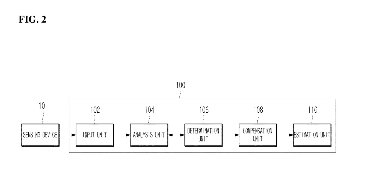
[0032]FIG. 1 is a block diagram showing a state in which a tire pressure estimating apparatus according to the present disclosure is connected to a sensing device, and FIG. 2 is a block diagram showing an example of the tire pressure estimating apparatus shown in FIG. 1.

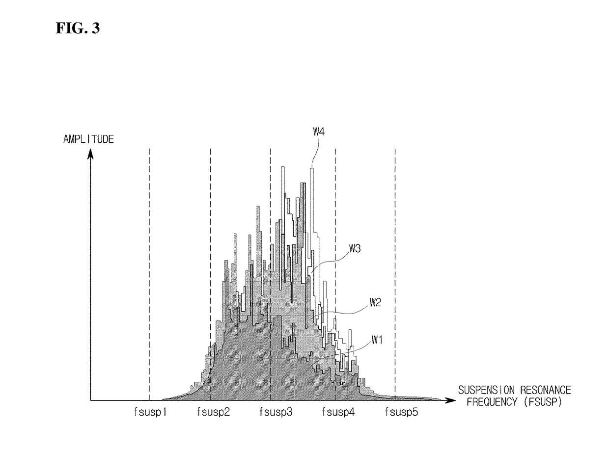
[0033]FIG. 3 is a graph showing a process of determining whether a determination unit shown in FIG. 2 outputs an amplified pulse in which a current load value is increased for a certain period of time.

[0034]FIG. 4 is a graph showing a comparison between a final tire pressure value estimated when a load is present and a final tire pressure value estimated when a load is absent, using a conventional tire pressure estimating apparatus.

[0035]FIG. 5 is a graph showing a comparison between a final tire pressure value estimated when a load is present and a final tire pressure value estimated when a load is absent, using a tire pressure estimating apparatus according to an embodiment of the present disclosure.

[0036]Referring...

second embodiment

[0072]FIG. 7 is a block diagram showing an example of a tire pressure estimating apparatus according to the present disclosure.

[0073]Referring to FIG. 7, a tire pressure estimating apparatus 700 according to a second embodiment of the present disclosure includes an input unit 702, an analysis unit 704, a determination unit 706, a compensation unit 708, and an estimation unit 710 in the same manner as that in the tire pressure estimating apparatus 100 of FIG. 2 according to the first embodiment of the present disclosure.

[0074]In this manner, functions of the input unit 702, the analysis unit 704, the determination unit 706, the compensation unit 708, and the estimation unit 710 of the tire pressure estimating apparatus 700 according to the second embodiment of the present disclosure and organic connection relation therebetween are the same as functions of the input unit 102 of FIG. 2, the analysis unit 104 of FIG. 2, the determination unit 106 of FIG. 2, the compensation unit 108 of ...


PUM


Abstract

Disclosed herein are a tire pressure estimating apparatus and a tire pressure estimating method thereof. The tire pressure estimating apparatus according to an embodiment of the present disclosure includes an input unit that receives a current wheel speed signal sensed by a sensing device, an analysis unit that analyzes a suspension resonance frequency value according to a current load value based on the input current wheel speed signal, a determination unit that determines whether the current load value is increased for a certain period of time, a compensation unit that compensates for a tire relative dynamic radius difference value and a tire relative air pressure difference value according to a load increase by applying a load compensation model to a tire dynamic radius analysis model, when the current load value is increased for the certain period of time, and an estimation unit that estimates a final tire pressure value based on the compensated tire relative dynamic radius difference value and tire relative air pressure difference value.

Description

CROSS-REFERENCE TO RELATED APPLICATION[0001]This application claims the benefit of Korean Patent Application No. 2016-0029569, filed on Mar. 11, 2016 in the Korean Intellectual Property Office, the disclosure of which is incorporated herein by reference.BACKGROUND[0002]1. Field[0003]Embodiments of the present disclosure relate to a tire pressure estimating apparatus and a tire pressure estimating method thereof.[0004]2. Description of the Related Art[0005]In general, a conventional tire pressure estimating apparatus determines whether a current pressure state of a tire is abnormal.[0006]For example, the conventional tire pressure estimating apparatus determines whether the current pressure state of the tire is abnormal using a current wheel speed.[0007]Since the conventional tire pressure estimating apparatus has a limitation in accurately and efficiently estimating the pressure state of the tire, an initial response to the current tire state is delayed, thereby causing a traffic ac...

Claims


Application Information

Patent Timeline
Patent Type & Authority Applications(United States)
IPC IPC(8): B60C23/04
CPCB60C23/0488B60C23/061B60C23/065B60C23/062
Inventor KIM, JOONG-HYUN
Owner HL MANDO CORP
Learn More