Ultrasonic device, ultrasonic module, and ultrasonic measurement apparatus

Active Publication Date: 2017-09-14
SEIKO EPSON CORP
View PDF4 Cites 2 Cited by
  • Summary
  • Abstract
  • Description
  • Claims
  • Application Information

AI Technical Summary

Benefits of technology

The technical effect of this patent is that it describes an ultrasonic device, module, and measurement apparatus that can improve distance resolution.

Problems solved by technology

In this case, there is a problem in that so-called tailing occurs in which not only a peak corresponding to the first waves but also a peak corresponding to the interface reflected waves is detected in a received signal which is output when the piezoelectric device receives the ultrasonic waves, and thus a distance resolution is reduced.

Method used


Image

  • Ultrasonic device, ultrasonic module, and ultrasonic measurement apparatus
  • Ultrasonic device, ultrasonic module, and ultrasonic measurement apparatus
  • Ultrasonic device, ultrasonic module, and ultrasonic measurement apparatus

Examples


first embodiment

[0058]Hereinafter, an ultrasonic apparatus according to a first embodiment will be described with reference to the drawings.

Configuration of Ultrasonic Measurement Apparatus

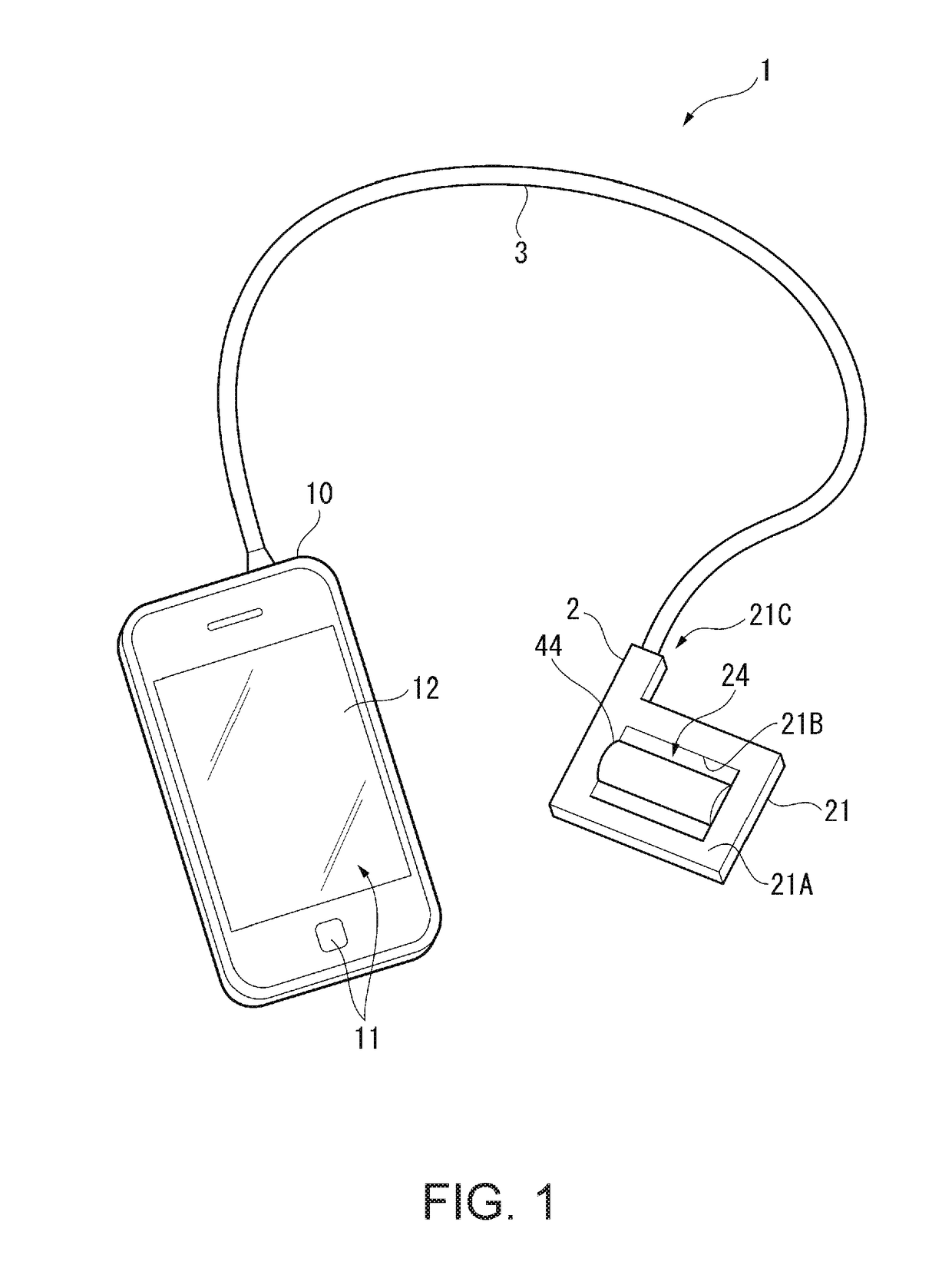
[0059]FIG. 1 is a perspective view illustrating a schematic configuration of an ultrasonic measurement apparatus 1 according to the present embodiment.

[0060]The ultrasonic measurement apparatus 1 of the present embodiment corresponds to an electronic apparatus, and includes, as illustrated in FIG. 1, an ultrasonic probe 2 and a control device 10 which is electrically connected to the ultrasonic probe 2 via a cable 3.

[0061]The ultrasonic measurement apparatus 1 sends ultrasonic waves into a living body from the ultrasonic probe 2 in a state in which the ultrasonic probe 2 is brought into contact with a surface of the living body (human body). Ultrasonic waves reflected from an organ in the living body are received by the ultrasonic probe 2, and, for example, an internal tomographic image of the living body is obta...

second embodiment

[0126]Next, an ultrasonic device according to a second embodiment will be described.

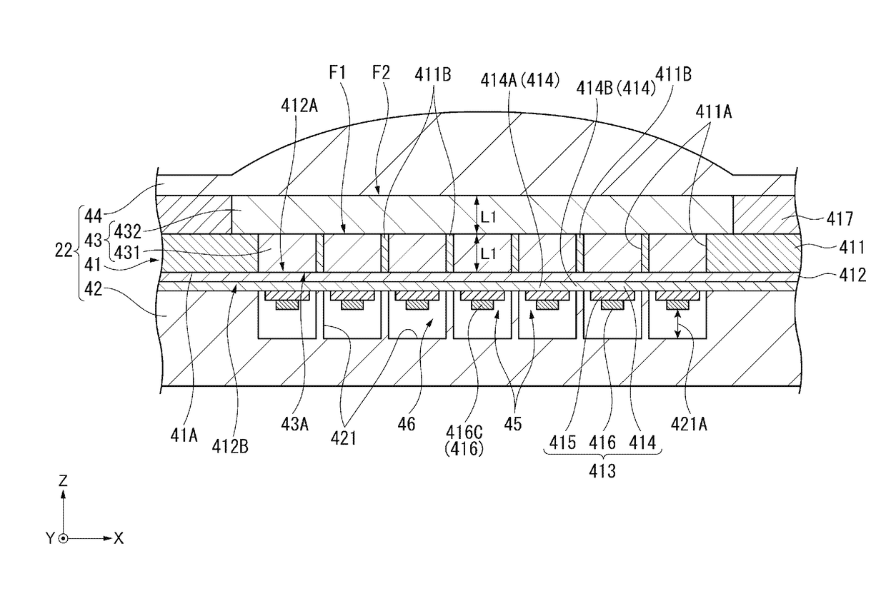
[0127]In the first embodiment, a description has been made of an exemplary configuration in which the ultrasonic device 22 includes the acoustic matching layer 43 formed of the first layer 431 and the second layer 432. In contrast, an ultrasonic device of the second embodiment is different from the ultrasonic device of the first embodiment in that an acoustic matching layer 47 is provided instead of the acoustic matching layer 43.

[0128]FIG. 12 is a sectional view schematically illustrating a section of an ultrasonic device 25 of the second embodiment.

[0129]As illustrated in FIG. 12, the ultrasonic device 25 is formed of an element board 41, a sealing plate 42, an acoustic matching layer 47, and an acoustic lens 44.

[0130]The element board 41 of the present embodiment is configured substantially in the same manner as in the first embodiment except that a depth dimension of the opening 411A is an intege...

third embodiment

[0137]Next, an ultrasonic device according to a third embodiment will be described.

[0138]In the second embodiment, a description has been made of an exemplary configuration in which the ultrasonic device 25 includes the acoustic lens 44 provided on the acoustic matching layer 47. In contrast, an ultrasonic device of the third embodiment is different from the ultrasonic device of the second embodiment in that an intermediate layer 48 is provided between the acoustic matching layer 47 and the acoustic lens 44.

[0139]FIG. 14 is a sectional view schematically illustrating a section of an ultrasonic device 26 according to the third embodiment.

[0140]As illustrated in FIG. 14, the ultrasonic device 26 is formed of an element board 41, a sealing plate 42, an acoustic matching layer 47, an intermediate layer 48, and an acoustic lens 44. The third embodiment is configured substantially in the same manner as the second embodiment except that the intermediate layer 48 includes a first intermedia...


PUM


Abstract

An ultrasonic device includes an ultrasonic transducer that has a vibration film and transmits an ultrasonic wave from a first surface side of the vibration film, an acoustic matching layer that is provided on the first surface side of the vibration film, and an acoustic lens that is provided on the acoustic matching layer on an opposite side to the vibration film, in which the acoustic matching layer is formed of even-numbered layers including a first layer and a second layer having acoustic impedance lower than acoustic impedance of each of the first layer and the acoustic lens, and the first layer and the second layer are disposed in this order toward the acoustic lens from the vibration film, and in which each of the first layer and the second layer has a thickness corresponding to an odd-numbered multiple of λ / 4 with a wavelength of the ultrasonic wave as λ.

Description

BACKGROUND[0001]1. Technical Field[0002]The present invention relates to an ultrasonic device, an ultrasonic module, and an ultrasonic measurement apparatus.[0003]2. Related Art[0004]In the related art, there is a piezoelectric device including a vibration film and a piezoelectric element as a vibrator causing the vibration film to vibrate, provided on the vibration film (for example, JP-A-2015-195351). The piezoelectric device transmits an ultrasonic wave by driving the piezoelectric element and causing the vibration film to vibrate, and receives an ultrasonic wave by detecting vibration of the vibration film caused by the ultrasonic wave with the piezoelectric element.[0005]The piezoelectric device disclosed in JP-A-2015-195351 further includes an acoustic matching layer provided on the vibration film, and an acoustic lens which is provided on the acoustic matching layer and has acoustic impedance similar to that of a living body as a measurement target. The piezoelectric device t...

Claims


Application Information

Patent Timeline
IPC IPC(8): H01L41/083A61B8/00B06B1/06B06B1/10H01L41/08H01L41/047
CPCH01L41/083H01L41/0825H01L41/0815A61B8/4483B06B1/06B06B1/10A61B8/4427H01L41/0475A61B8/4411B06B1/0688A61B8/4281A61B8/4444G01S7/52079H10N30/50H10N30/875H10N30/101H10N30/708
Inventor NAKAMURA, TOMOAKI
Owner SEIKO EPSON CORP
Why Eureka
Try Eureka