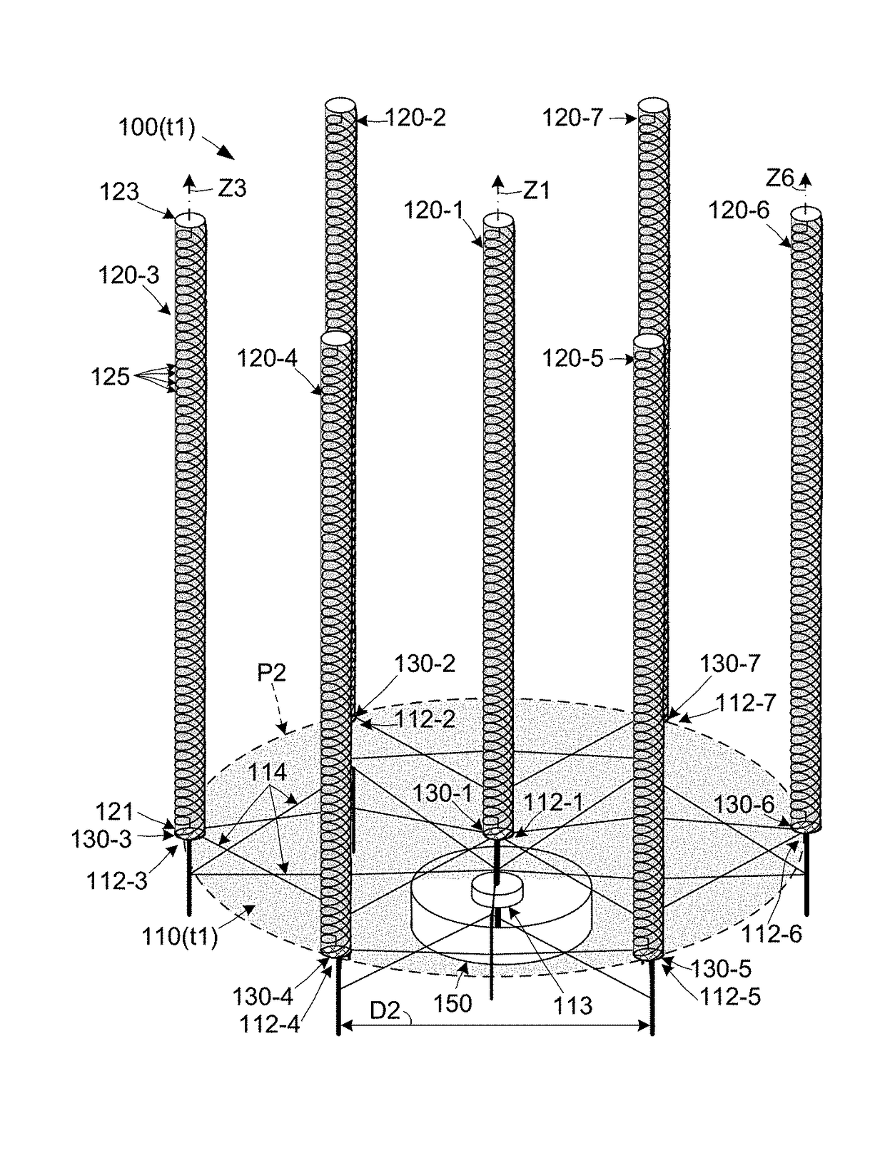
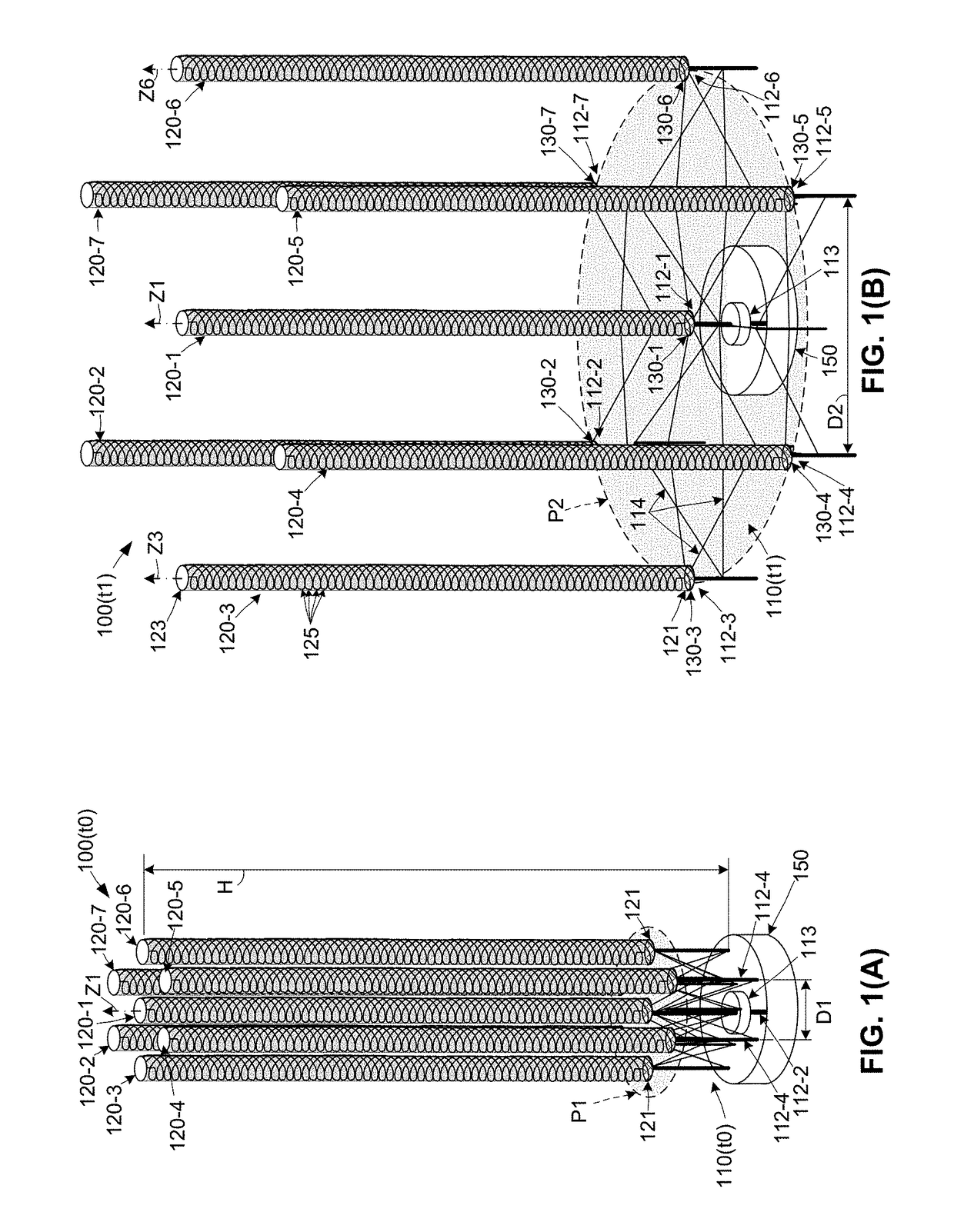
[0004]The present invention is directed to an antenna assembly including an array of multifilar (e.g., quadrifilar, hexifilar or octofilar) helix antenna (MHA) structures that are rigidly maintained in an optimal (e.g., hexagonal) phased array configuration by a lightweight linkage, and are controlled by a central antenna feed circuit such that the MHA structures collectively perform phased array antenna operations capable of maintaining a circularly polarized radiation pattern while requiring an approximately four-times (4X) smaller physical area than an equal gain aperture-type antenna (e.g., parabolic dish). Each MHA structure includes multiple (e.g., four, six or eight) helical filar elements disposed in a spaced-apart relationship around a central axis (i.e., disposed within an elongated cylindrical volume), with each helical filar element coupled by way of intervening electronics to the central antenna feed circuit, which in turn is configured to transmit signals to and receive signals from the multiple helical filar elements in accordance with known phased array operating practices. The lightweight linkage includes several support structures connected by bar-like linkage elements, and a fixed end of each MHA structure is fixedly connected to one of the support structures such that all of the MHA structures extend parallel to each other from the linkage. The resulting phased array antenna assembly achieves a highly-directive beam at higher gain values (43.4 dBi or greater) and higher aperture (antenna) efficiencies (i.e., 92% or greater) than conventional deployable antenna approaches by multiplying the gain of each MHA structure by the number of MHA structures in the array. Moreover, by rigidly arranging the MHA structures in an optimal array configuration (pattern), phased array antenna assemblies produced in accordance with the present invention achieve an equivalent effective antenna area (EFA; i.e., target antenna area) consistent with conventional antennas requiring four times the physical area. Further, each MHA structure utilizes multiple helical elements to generate a single forward lobe, which obviates the need for a dedicated ground plane structure required by single helical and other antenna topologies, whereby phased array antenna assemblies produced in accordance with the present invention have a significant weight and space advantage over conventional deployable antenna approaches. Accordingly, by utilizing an array of MHA structures, a lightweight linkage and the central antenna feed circuit discussed above, the present invention facilitates the production of high-gain, high-efficiency phased array antenna assemblies exhibiting highly accurate beam pointing capabilities that are difficult to achieve using conventional antenna approaches, and also have lightweight architectures and scalable footprints that can be optimized for use on a wide range of microsatellite platforms.
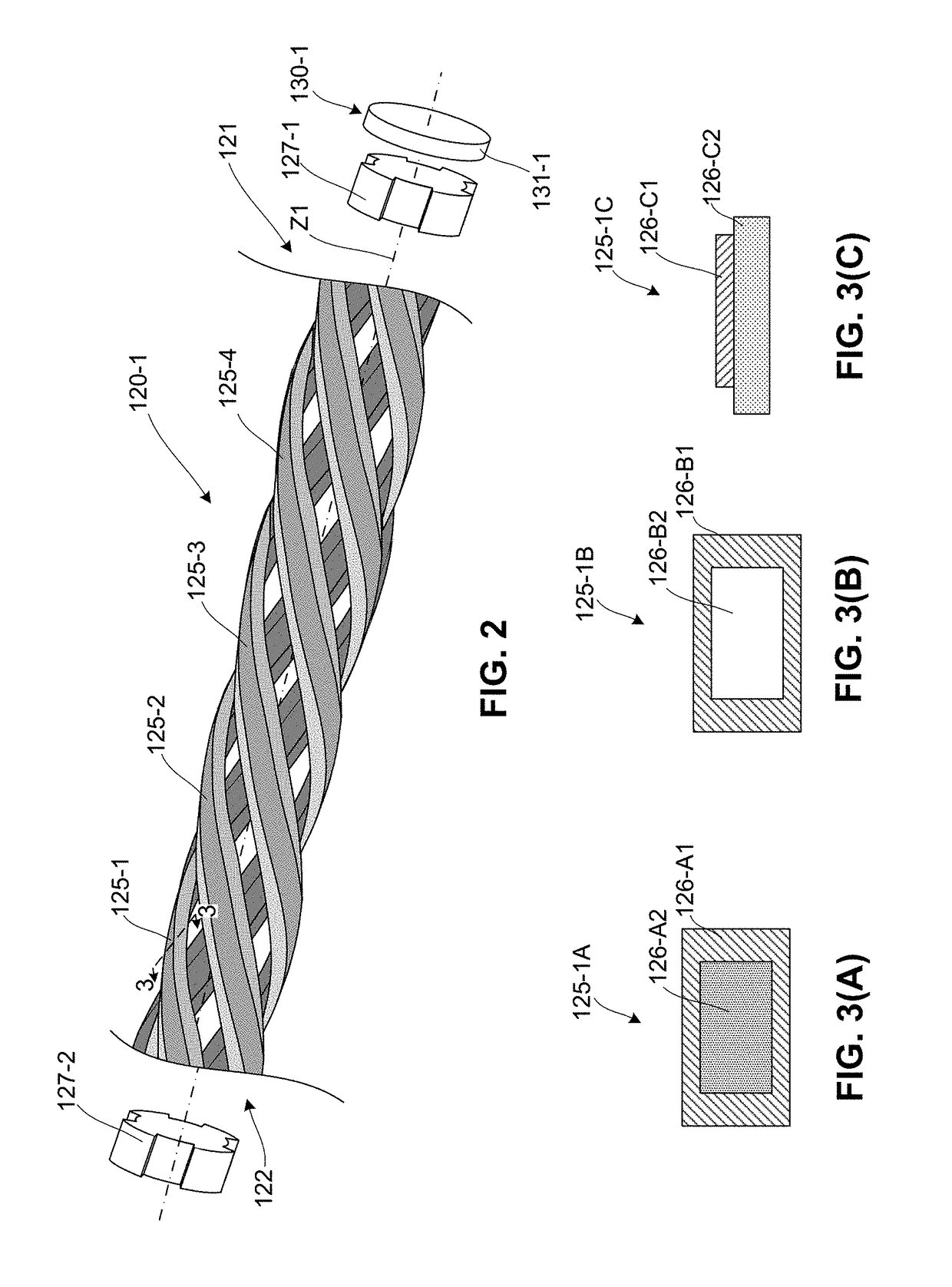
[0005]According to a presently preferred embodiment, each MHA structure includes helical filar elements that are modified to minimize weight and to enable phased array operations, whereby the MHA structures are further optimized for microsatellite platforms. In a first specific embodiment, each of the helical filar elements utilized by the MHA structures is produced by disposing (e.g., plating or printing) a metal or other conductive material on a lightweight base structure (e.g., a liquid crystal polymer core or a flexible plastic substrate), and then bending the composite structure into the required helical shape. In a second specific embodiment, each of the four helical filar elements includes a thin-walled cylindrical metal (e.g., aluminum) tube surrounding a central vacuum air-filled void that is bent into the required helical configuration. Both the first and second specific embodiments provide helical filar elements having substantially lower weight/mass values than solid wire filars used by conventional single filar and multiple filar antennas. In another embodiment, each MHA structure further includes two lightweight (e.g., plastic or polymer) spacers respectively secure opposite (i.e., fixed and free) ends of the helical filar elements, and a local feed circuit board that is fixedly attached to the spacer connected to the fixed end of each helical filar element. The spacers are configured to secure and maintain the helical filar elements in a spaced-apart relationship such that the helical filar elements are reliably offset by common (i.e., equal or uniform) radial distances (e.g., 90°, 60° or 45°, depending on the number of elements) relative to the central axis, thereby facilitating low-cost assembly. The local feed circuit board is electrically connected to the helical filar elements of each M-QHA structure, and functions to coordinate the transmission of signals from the filar elements to the central antenna feed circuit in a manner described below. In an exemplary practical embodiment, each MHA element is a modified quadrifilar helix antenna (M-QHA) structure including four modified (lightweight) filar elements, but in other embodiments helical hexifilar or octofilar topologies may be utilized to increase gain and improve the compaction ratio.
[0006]According to another specific embodiment, the phased array antenna assemblies of the present invention include local antenna feed circuits that function in cooperation with the central antenna feed circuit to implement phased array operations. Each local antenna feed circuit is disposed adjacent to an associated said MHA structure (e.g., mounted on the support structure to which the associated MHA structure is connected) and electrically coupled between the central antenna feed circuit and the associated MHA structure's helical filar elements (e.g., by way of wires extending along the linkage elements and support structures of the linkage). In an exemplary embodiment, each local antenna feed circuit includes first and second hybrid couplers connected to each of four helical filar elements, and a third hybrid coupler coupled between the first and second hybrid couplers and an amplifier, which in turn is coupled to the central antenna feed circuit. With this arrangement, phased coupling of the four helical filar elements is controlled locally (i.e., by each local antenna feed circuit) in order to simplify operations of the central antenna feed circuit. In another exemplary embodiment, each local antenna feed circuit includes both a low-noise amplifier (e.g., a SiGe MMIC) for signal reception, and a power amplifier (e.g., a GaN HEMI) for signal transmission. To facilitate separate send and receive operating modes, a first (e.g., RF) switch is operably connected between the amplifiers and the third hybrid coupler, and a second switch is operably coupled between the amplifiers and the central antenna feed circuit. With this arrangement, the switches are configured to operably couple the low-noise amplifier between the central antenna feed circuit and the third hybrid coupler during each rec

