Complex Antenna

Active Publication Date: 2017-03-23
WISTRON NEWEB
View PDF4 Cites 1 Cited by
  • Summary
  • Abstract
  • Description
  • Claims
  • Application Information

AI Technical Summary

Benefits of technology

The present invention is a complex antenna that meets size and cost requirements, has high antenna gain and beam coverage, and offers adaptive beam alignment. This means that the antenna can adjust its beam to match the specific needs of the user.

Problems solved by technology

However, the beamwidth of the panel-type antenna in the horizontal plane is narrow, meaning that its beam coverage rate is low, and hence the panel-type antenna can hardly be mounted easily and accurately.
Worst of all, the panel-type antenna lacks adaptive beam alignment capabilities.
An antenna motor however costs a lot of money and sets limits on installation conditions, which cannot accommodate the trend for smaller-sized electronic products. FIG. 1 is a schematic diagram illustrating a complex antenna 10.

Method used


Image

  • Complex Antenna
  • Complex Antenna
  • Complex Antenna

Examples


Embodiment Construction

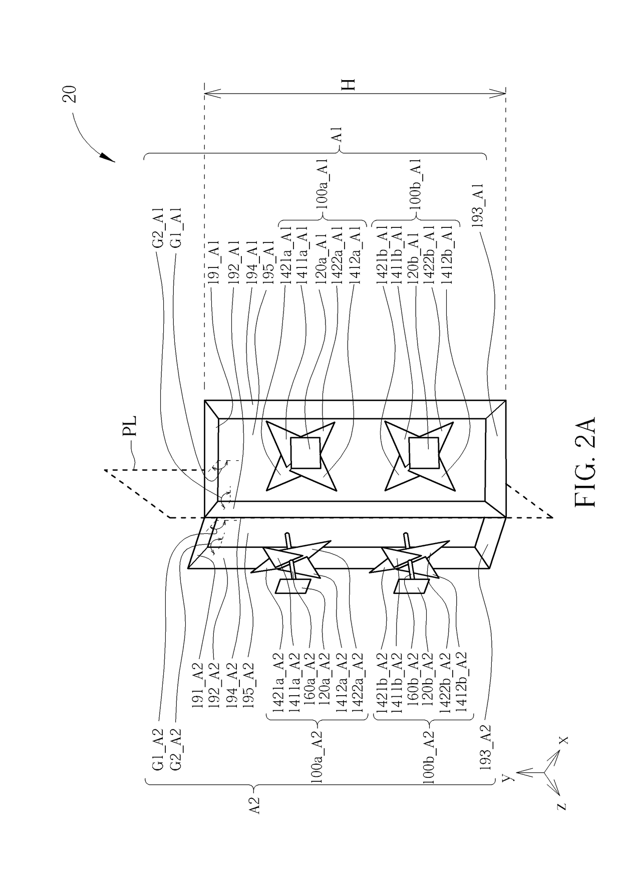
[0021]Please refer to FIG. 2A and FIG. 2B. FIG. 2A is a schematic diagram illustrating a complex antenna 20 according to an embodiment of the present invention. FIG. 2B is a schematic diagram illustrating a top view of the complex antenna 20. The complex antenna 20 comprises antenna units A1 and A2. The antenna unit A1 comprises antenna elements 100a_A1, 100b_A1 and a reflective unit 190_A1; the antenna unit A2 comprises antenna elements 100a_A2, 100b_A2 and a reflective unit 190_A2. The antenna elements 100a_A1 and 100b_A1 comprise reflective plates 120a_A1, 120b_A1, radiation units 141a_A1, 142a_A1, 141b_A1, 142b_A1 and supporting elements 160a_A1, 160b_A1 respectively; the antenna elements 100a_A2 and 100b_A2 comprise reflective plates 120a_A2, 120b_A2, radiation units 141a_A2, 142a_A2, 141b_A2, 142b_A2 and supporting elements 160a_A2, 160b_A2 respectively. The complex antenna 20 can switch between a first single-beam mode and a second single-beam mode so as to transmit or receiv...


PUM


Abstract

A complex antenna configured to transmit or receive radio-frequency signals includes a first antenna unit and a second antenna unit. The first antenna unit is fixed to the second antenna unit with a first included angle, and the complex antenna does not have a closed annular structure.

Description

BACKGROUND OF THE INVENTION[0001]1. Field of the Invention[0002]The present invention is related to a complex antenna, and more particularly, to a complex antenna which suits both dimension and cost requirements, ensures high antenna gain value and beam coverage rate, and offers adaptive beam alignment capabilities.[0003]2. Description of the Prior Art[0004]Electronic products with wireless communication functionalities utilize antennas to emit and receive radio waves, to transmit or exchange radio signals, so as to access a wireless communication network. With the advance of wireless communication technology, demand for transmission capacity and wireless network ability has grown dramatically in recent years. A long term evolution (LTE) wireless communication system and a wireless local area network standard IEEE 802.11n both support multi-input multi-output (MIMO) communication technology, which can vastly increase system throughput and transmission distance without increasing sys...

Claims


Application Information

Patent Timeline
IPC IPC(8): H01Q9/06H01Q1/36H01Q15/14H01Q21/06
CPCH01Q9/065H01Q15/14H01Q1/36H01Q21/065H01Q3/24H01Q15/165H01Q19/108H01Q21/26H01Q21/28
Inventor JAN, CHENG-GENGHSU, CHIEH-SHENG
Owner WISTRON NEWEB
Why Eureka
Try Eureka