Power conversion apparatus
a technology of power conversion apparatus and power conversion, which is applied in the direction of thermometers using value differences, instruments, heat measurement, etc., can solve the problems of reducing the reliability of heat transfer map data, affecting the and affecting the effectiveness of element performance, so as to reduce the safety margin set to absorb variations, reduce the effect of excessive application of output limitation and effective realization of element performan
- Summary
- Abstract
- Description
- Claims
- Application Information
AI Technical Summary
Benefits of technology
Problems solved by technology
Method used
Image
Examples
first embodiment
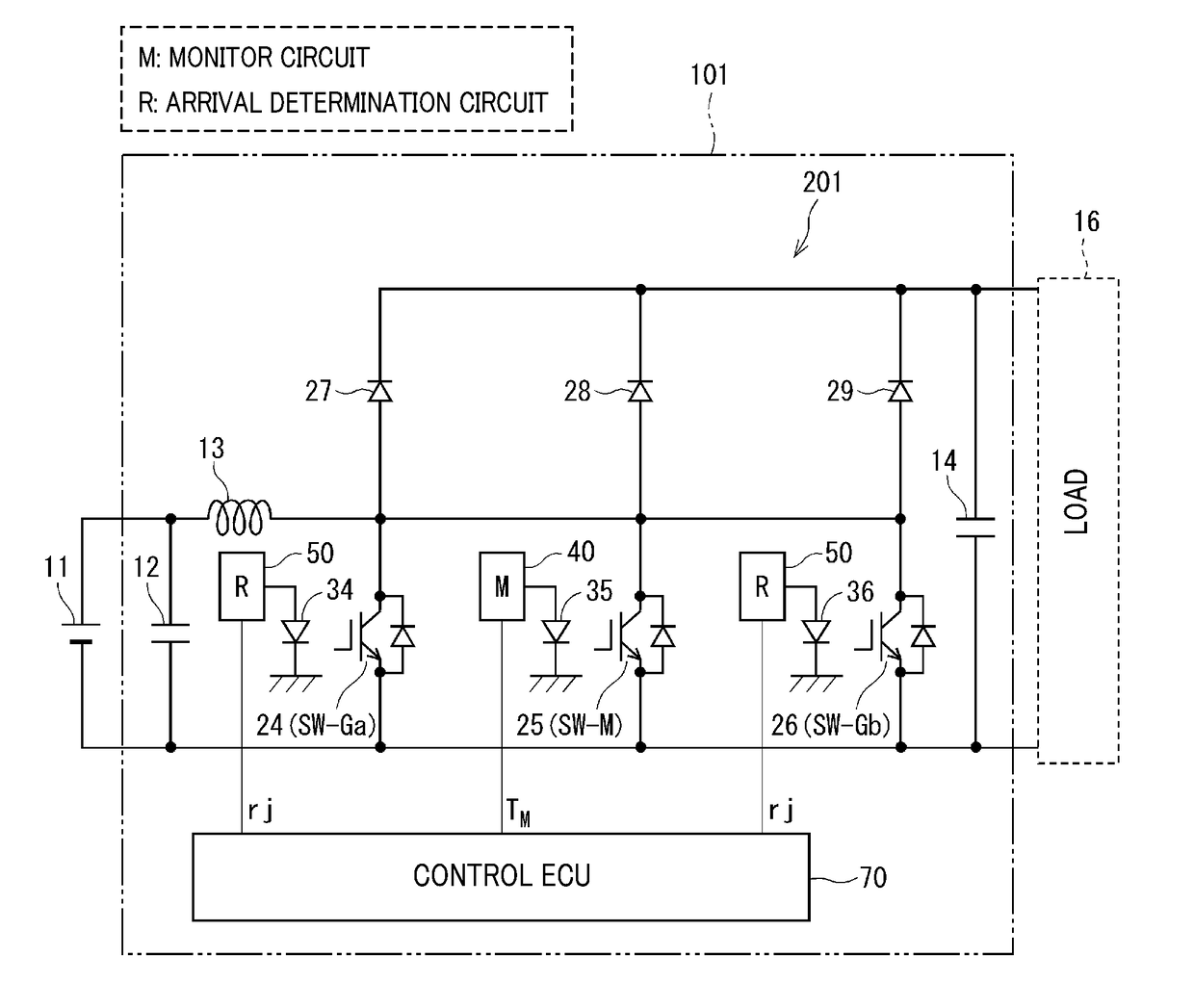
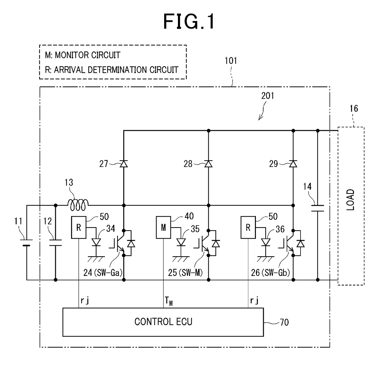
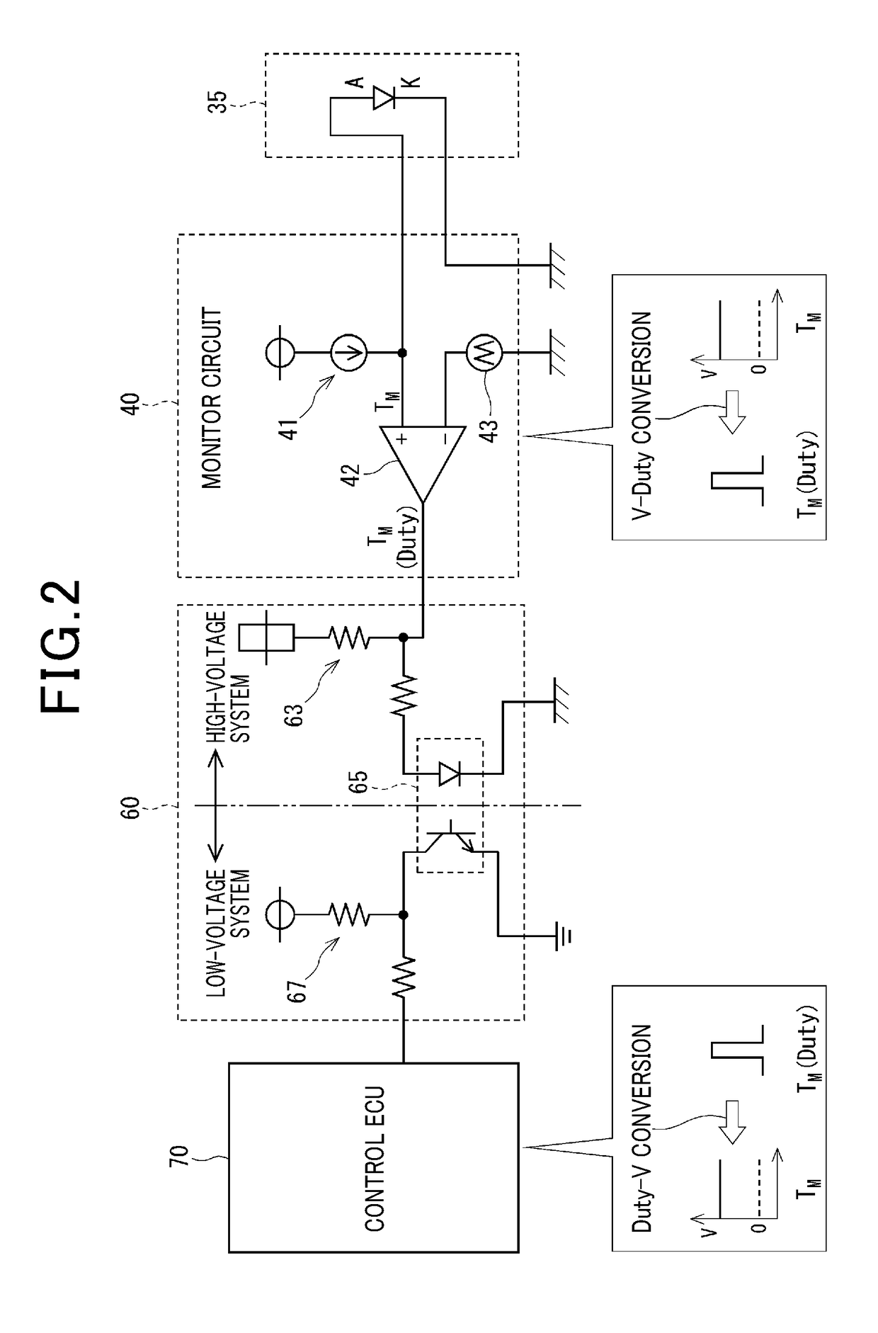
[0044]A power conversion apparatus according to the first embodiment will be described with reference to FIGS. 1 to 8B. Here, the first and second embodiments both reference FIGS. 1 to 3.
[0045]As shown in FIG. 1, a power conversion apparatus 101 according to the first and second embodiments include a boost converter 201, temperature-sensitive diodes 34, 35, and 36, a monitor circuit 40, arrival determination circuits 50, a control electronic control unit (ECU) 70, and the like. The boost converter 201 serves as a power conversion circuit. The temperature-sensitive diodes 34, 35, and 36 serve as temperature output units (element temperature output units).
[0046]The boost converter 201 is connected between a battery 11 and a load 16. The boost converter 201 boosts the direct-current voltage of the battery 11 and outputs the boosted direct-current voltage to the load 16. For example, the load 16 may be an inverter that is a power conversion circuit according to the fifth embodiment.
[004...
second embodiment
[0148]Next, a configuration of the control ECU 702 according to the second embodiment and the difference with the output limitation process according to the first embodiment will be described with reference to FIGS. 9 to 12. FIGS. 9, 10A, 10B, and 12 respectively correspond to FIGS. 4, 8A, 8B, and 7 according to the first embodiment. In addition, FIG. 11 is a time chart of a format similar to that of FIGS. 5 and 6 according to the first embodiment.
[0149]As shown in FIG. 9, in the control ECU 702 according to the second embodiment, an analog output correcting unit 74 is further provided in the control ECU 701 according to the first embodiment. The analog output correcting unit 74 corrects the analog output errors ΔTanaGa, ΔTanaM, and ΔTanaGb of the temperature-sensitive diodes 34, 35, and 36.
[0150]The analog output correcting unit 74 stores predetermined correction values of the analog output errors ΔTanaGa, ΔTanaM, and ΔTanaGb for each individual temperature-sensitive diode in a non...
third embodiment
[0169]Next, configurations of a power conversion apparatus 103 and a control ECU 703, and the like according to a third embodiment will be described with reference to FIGS. 13 to 16. FIG. 13 corresponds to FIG. 1 according to the first and second embodiments. FIG. 13 shows the configuration of the power conversion apparatus 103 that includes the boost converter 201 as the power conversion circuit. FIG. 15 is a time chart of a format similar to that of FIGS. 5, 6, and 11. FIG. 16 corresponds to FIGS. 7 and 12.
[0170]As shown in FIG. 13, in the power conversion apparatus 103 according to the third embodiment, both the monitor circuit 40 and the arrival determination circuit 50 are provided in correspondence to the switching element 25 that is the monitored element SW-M. That is, three arrival determination circuits 50 are provided for the three switching elements 24, 25, and 26.
[0171]The arrival determination circuit 50 for the monitored element SW-M outputs the arrival determination s...
PUM
| Property | Measurement | Unit |
|---|---|---|
| electric power | aaaaa | aaaaa |
| temperature | aaaaa | aaaaa |
| temperatures | aaaaa | aaaaa |
Abstract
Description
Claims
Application Information
 - R&D
- Intellectual Property
- Life Sciences
- Materials
- Tech Scout
- Unparalleled Data Quality
- Higher Quality Content
- 60% Fewer Hallucinations
Browse by: Latest US Patents, China's latest patents, Technical Efficacy Thesaurus, Application Domain, Technology Topic, Popular Technical Reports.
© 2025 PatSnap. All rights reserved.Legal|Privacy policy|Modern Slavery Act Transparency Statement|Sitemap|About US| Contact US: help@patsnap.com


