Articulatable prosthetic valve

a prosthetic valve and articulation technology, applied in the field of prosthetic cardiac valves, can solve the problems of decreased cardiac output and increased total stroke volume, and achieve the effect of facilitating lateral movement and intracardiac positioning of the downstream fram

a prosthetic valve and articulation technology, applied in the field of prosthetic cardiac valves, can solve the problems of decreased cardiac output and increased total stroke volume, and achieve the effect of facilitating lateral movement and intracardiac positioning of the downstream fram

US20170266003A1Active Publication Date: 2017-09-21CARDIOVALVE LTD

Image

  • Articulatable prosthetic valve
  • Articulatable prosthetic valve
  • Articulatable prosthetic valve

Examples


Embodiment Construction

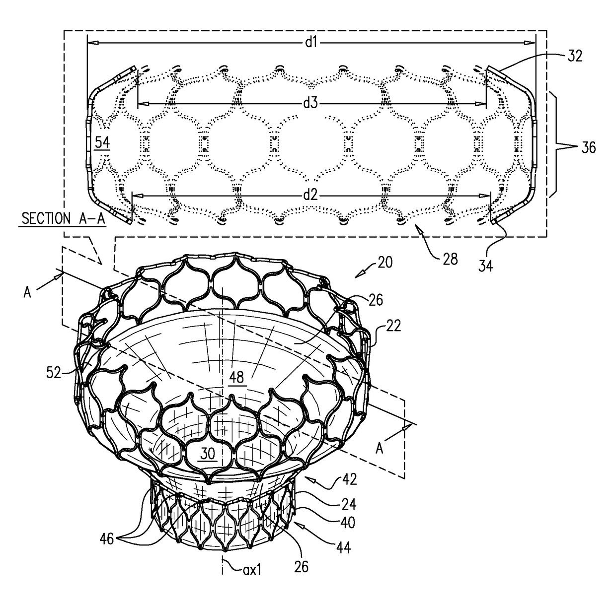
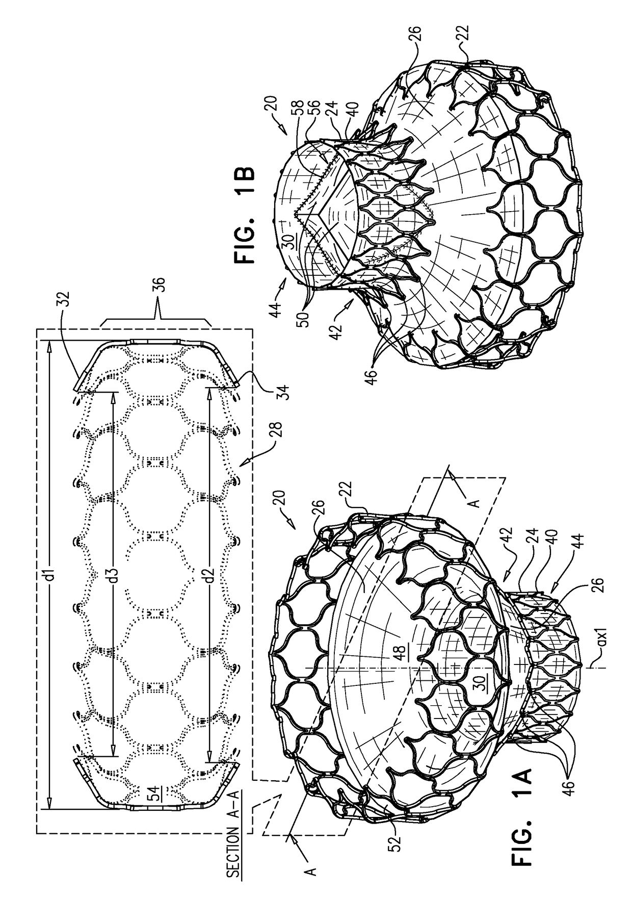
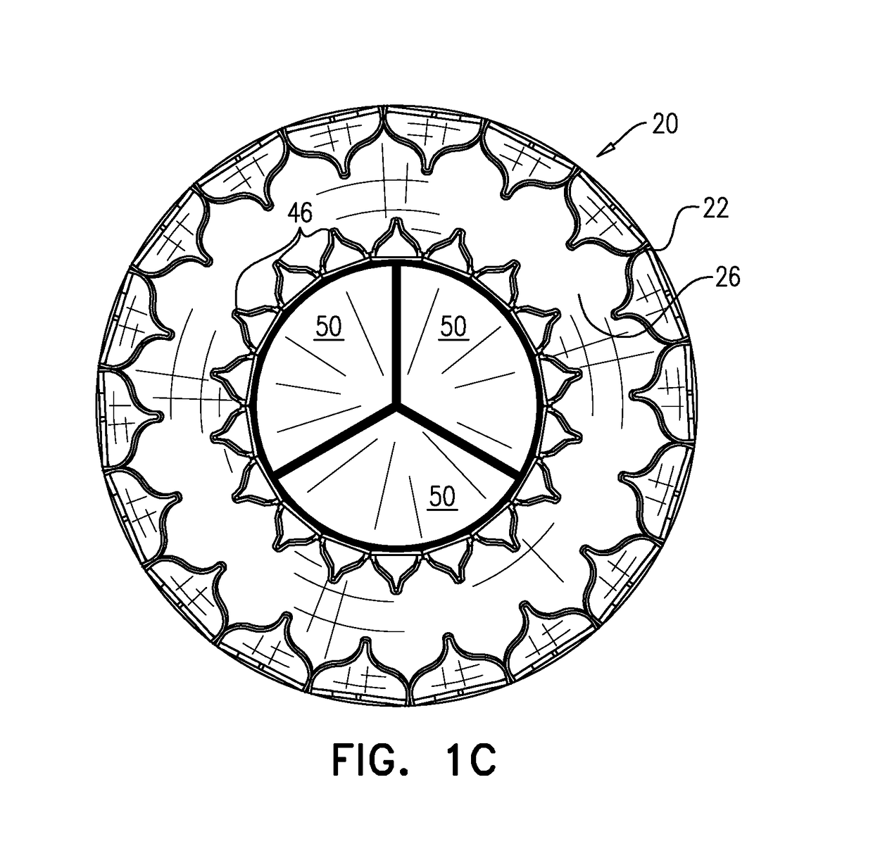
[0476]Reference is made to FIGS. 1A-C and 2, which are schematic illustrations of an implant 20 comprising an upstream frame 22, a downstream frame 24 that is distinct from the upstream frame, and a flexible sheet 26 connecting the upstream and downstream frames, in accordance with some applications of the invention. FIGS. 1A-B show respective perspective views of implant 20, FIG. 1C shows an end view of the implant, and FIGS. 2A-B show side views of the implant. Typically upstream frame 22 and downstream frame 24 each define (or are each defined by) a regularly tiled distribution of cells (e.g., a two-dimensional shape) that provides the three-dimensional shape of the frame. Alternatively, the upstream frame and / or the downstream frame may have a different structure, e.g., may comprise a wire frame and / or a braided mesh.

[0477]Frame 22 has a generally toroid shape, having an upstream end 32, a downstream end 34, and a mid portion 36 therebetween. Mid portion 36 has a width d1 that i...


PUM


Abstract

A rod (508) is transfemorally advanceable to the heart. An implant (460) comprises (i) a first frame (462), compressed around a first longitudinal site of a distal portion of the rod, (ii) a second frame (464), compressed around a third longitudinal site of the distal portion, (iii) a valve member (50), disposed within the second frame, and (iv) a flexible sheet (466), coupling the first frame to the second frame, and disposed around a second longitudinal site of the distal portion, the second longitudinal site being between the first longitudinal site and the third longitudinal site. An extracorporeal controller (569) is coupled to a proximal portion of the rod, and is operably coupled to the distal portion of the rod. Operating the controller bends the distal portion of the rod causing articulation between the frames. Other embodiments are also described.

Description

CROSS-REFERENCES TO RELATED APPLICATIONS[0001]The present application claims priority from:[0002](i) US Provisional Patent Application 62 / 030,715 to Hammer et al., filed Jul. 30, 2014, and entitled “Prosthetic valve with crown”; and[0003](ii) US Provisional Patent Application 62 / 139,854 to Hammer et al., filed Mar. 30, 2015, and entitled “Prosthetic valve with crown.”[0004]The present application is related to (i) PCT patent application IL2014 / 050087 to Hammer et al., filed Jan. 23, 2014, entitled “Ventricularly-anchored prosthetic valves”, which published as WO 2014 / 115149, and (ii) U.S. patent application Ser. No. 14 / 763,004 to Hammer et al., entitled “Ventricularly-anchored prosthetic valves”, which is a US National Phase of PCT IL2014 / 050087. All of the above are incorporated herein by reference.FIELD OF THE INVENTION[0005]Some applications of the present invention relate in general to valve replacement.[0006]More specifically, some applications of the present invention relate t...

Claims


Application Information

Patent Timeline
21 Sep 2017
Publication
US20170266003A1
IPC
A61F2/24
CPC
A61F2/2436; A61F2/2418; A61F2250/0039; A61F2230/001; A61F2230/0067; A61F2220/0025; A61F2/2439; A61F2002/828
Inventors
HAMMER, TAL; IAMBERGER, MENI