
Electromagnetic damper system

a damper system and electromagnetic technology, applied in the direction of vehicle components, vehicle suspensions, transportation and packaging, etc., can solve the problems of lowering the marketability of vehicles, damping force may be produced too late, and vehicle comfort may be lowered, so as to improve the riding comfort of vehicles and reduce time delays

Active Publication Date: 2017-09-21
HONDA MOTOR CO LTD
View PDF0 Cites 6 Cited by
  • Summary
  • Abstract
  • Description
  • Claims
  • Application Information

AI Technical Summary

Benefits of technology

This patent text describes a system that reduces the operating sound of a motor in a vehicle to improve its marketability. The system uses both an electromagnetic damper and a hydraulic damper, with a filtering process applied to the electromagnetic damper in the high frequency range. The technique improves riding comfortableness of the vehicle even in cases where a high input velocity vibration is input, by damping the vibration without a delay using the electromagnetic damper.

Problems solved by technology

The occurrence of the operating sound of the motor may lower the marketability of a vehicle.
However, in the system that uses only the electromagnetic damper, the vibration damping force may be produced too late for an input at a high input velocity of the vibration, and the riding comfortableness of the vehicle may be lowered.

Method used


Image

  • Electromagnetic damper system
  • Electromagnetic damper system
  • Electromagnetic damper system

Examples


Embodiment Construction

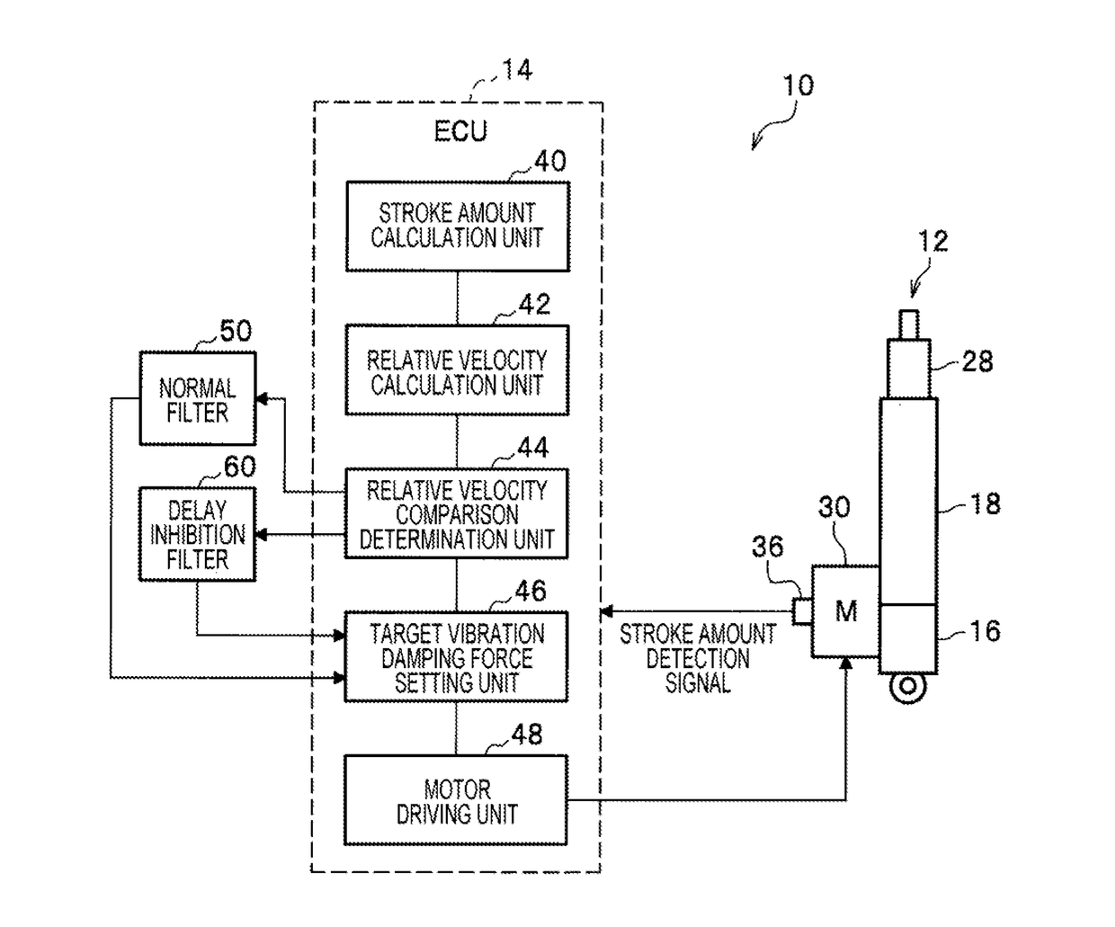
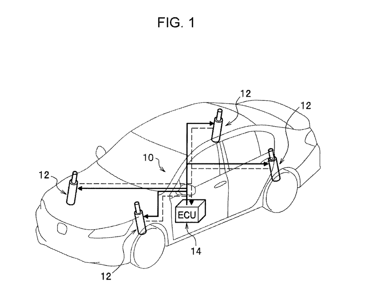
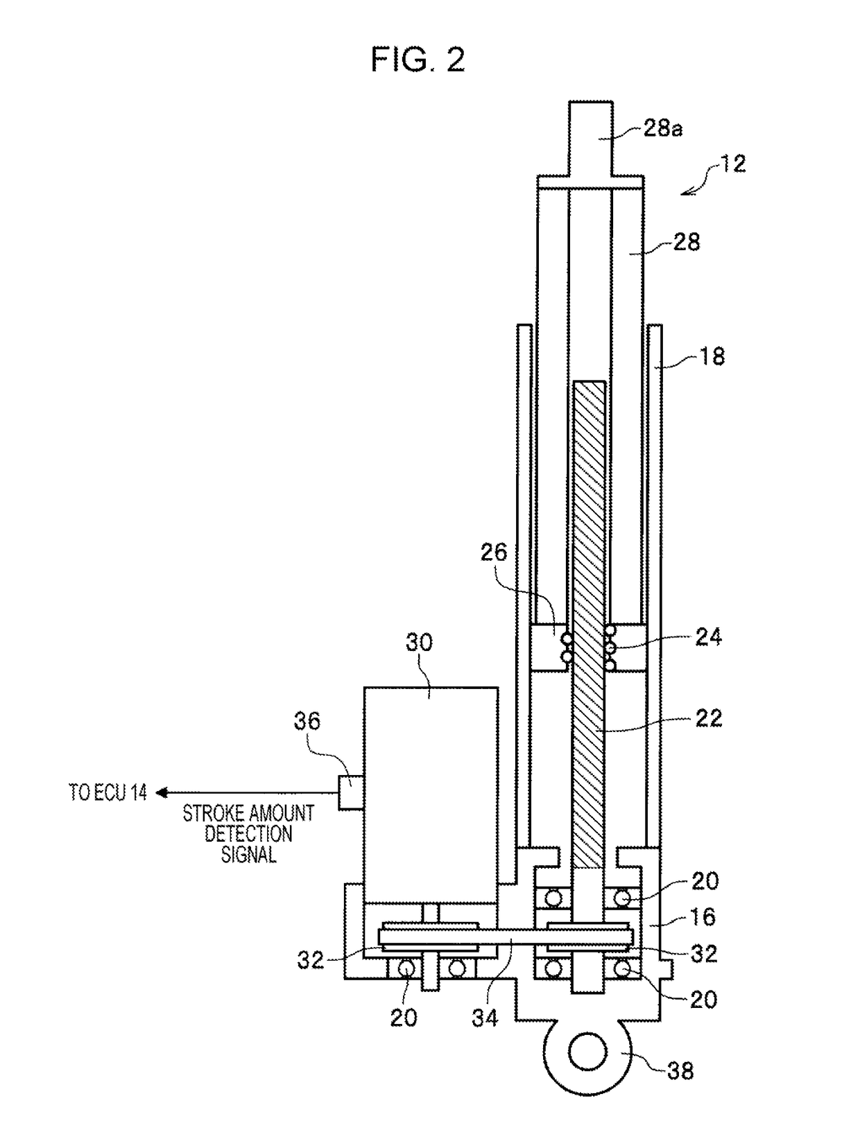
[0023]An embodiment of the present disclosure will next be described in detail appropriately with reference to drawings. FIG. 1 is a schematic configuration diagram of a state where an electromagnetic damper system according to the embodiment of the present disclosure is installed in a vehicle. FIG. 2 is a partial cross-sectional structure diagram of an electromagnetic damper that is illustrated in FIG. 1. FIG. 3 is a configuration block diagram of the electromagnetic damper system.

[0024]As illustrated in FIG. 1, an electromagnetic damper system 10 according to this embodiment that is installed in the vehicle is configured to include plural electromagnetic dampers 12 and an electronic control unit (hereinafter referred to as ECU) 14. In this embodiment, four electromagnetic dampers 12 are arranged for both of front wheels (a left front wheel and a right front wheel) and rear wheels (a left rear wheel and a right rear wheel). However, embodiments are not limited to this, but the elec...


PUM


Abstract

A relative velocity between a sprung mass and an unsprung mass of a vehicle is calculated by differentiating a stroke amount of an electromagnetic damper with respect to time. The relative velocity is compared with a predetermined value that is set in advance, and a determination is made whether or not the relative velocity is the predetermined value or higher. In a case where the relative velocity is lower than the predetermined value (relative velocity<predetermined value), a normal filter is selected, and a gain G of only an unsprung resonance frequency range is increased. On the other hand, in a case where the relative velocity is the predetermined value or higher (relative velocity≧predetermined value), a delay inhibition filter is selected, and a gain of a high frequency range is increased compared to the normal filter.

Description

CROSS REFERENCES TO RELATED APPLICATIONS[0001]The present application claims priority under 35 U.S.C. §119 to Japanese Patent Application No. 2016-051966, filed Mar. 16, 2016, entitled “Electromagnetic Damper System.” The contents of this application are incorporated herein by reference in their entirety.BACKGROUND[0002]1. Field[0003]The present disclosure relates to an electromagnetic damper system that includes an electromagnetic damper which produces a vibration damping force.[0004]2. Description of the Related Art[0005]In recent years, in order to improve riding comfortableness of the vehicle, study and development of an electromagnetic damper that is capable of actively controlling a vibration damping force have been advanced. For example, Japanese Unexamined Patent Application Publication No. 2010-253989 discloses a damper system in which a propulsive force production device (the electromagnetic damper) which produces propulsive forces for a sprung mass and an unsprung mass an...

Claims


Application Information

Patent Timeline
Patent Type & Authority Applications(United States)
IPC IPC(8): B60G17/06B60G17/019B60G17/015
CPCB60G17/06B60G17/01933B60G17/0152B60G17/018B60G2400/202B60G2500/10
Inventor TOYOHIRA, TOMOYAKATO, TAKAFUMIONO, SATOSHIYONEDA, ATSUHIKO
Owner HONDA MOTOR CO LTD
Learn More