Torsion filtering mechanism having a cam track

a filtering mechanism and cam track technology, applied in mechanical equipment, springs/dampers, vibration suppression adjustments, etc., can solve the problems of centrifugal effects, large trial and error, and relatively bulky springs of coil springs, and achieve the effect of simple cam profil

Active Publication Date: 2017-09-21
VALEO EMBRAYAGES SAS
View PDF6 Cites 7 Cited by
  • Summary
  • Abstract
  • Description
  • Claims
  • Application Information

AI Technical Summary

Benefits of technology

[0006]The invention aims to eliminate the disadvantages of the existing art and to propose a

Problems solved by technology

These dampers having coil springs are relatively bulky and do not offer wide design freedom for adapting, as necessary, the angular stiffness between the rotating members.
Their dynamic behavior, bearing in mind centrifugal effects, is furthermore difficult to manage, especially due to friction between the springs and the walls of their receptacl

Method used


Image

  • Torsion filtering mechanism having a cam track
  • Torsion filtering mechanism having a cam track
  • Torsion filtering mechanism having a cam track

Examples


Embodiment Construction

)

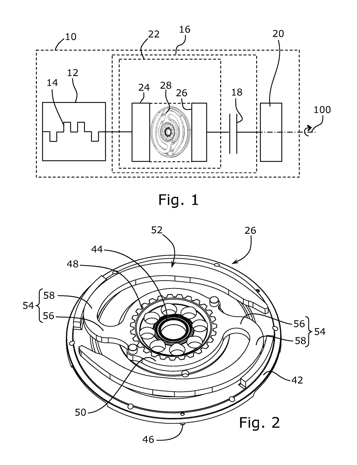
[0059]FIG. 1 illustrates a motor vehicle propulsion assemblage 10 having an internal combustion engine 12 whose crankshaft 14 drives a kinematic transmission drivetrain 16 having a dry clutch 18 arranged upstream from a gearbox input shaft 20. Disposed kinematically between crankshaft 14 and friction clutch 18 in kinematic transmission drivetrain 16 is a torsion filtering mechanism 22 that constitutes a dual mass flywheel and has an input member constituted by a primary flywheel 24 integral with crankshaft 14 and an output member constituted by a secondary flywheel 26 integral with a reaction plate of clutch 18 or made as a single piece therewith. Elastic members 28 are interposed between primary flywheel 24 and secondary flywheel 26 so as to operate in the context of angular position fluctuations between primary flywheel 24 and secondary flywheel 26. Crankshaft 14, damping mechanism 22, clutch 18, and input shaft 20 of the gearbox rotate around a single axis of revolution 100.

[006...


PUM


Abstract

A torsion filtering mechanism (22) has a first rotating member (24), a second rotating member (26) movable with respect to the first rotating member (24), a cam track (60) rotating with one (24) of the rotating members, and at least one associated cam follower (36) carried by the other (26) rotating member. The cam track (60) has, in a section plane perpendicular to the axis of revolution, a profile constituted by a plurality of circular arcs (A0, A1, A2, A3, A4) adjacent pairwise and having an intersection point pairwise. Any two adjacent circular arcs from among the circular arcs have different finite or infinite radii of curvature, and indistinguishable tangents at the intersection point.

Description

CROSS-REFERENCE TO RELATED APPLICATIONS AND CLAIM TO PRIORITY[0001]This application is related to Patent Application No. 1652210 and Patent Application No. 1652211 both filed Mar. 16, 2016 in France, the disclosures of which are incorporated herein by reference and to which priority is claimed.FIELD OF THE INVENTION[0002]The invention relates to a torsion filtering mechanism and more specifically to a torsion filtering mechanism for a torque transmission device, in particular for a motor vehicle, specifically for a clutch device, for example for a dual mass flywheel, for a pendulum oscillator, for a long-travel damper, placed upstream or downstream from a friction clutch or downstream from a torque converter.BACKGROUND OF THE INVENTION[0003]Torque converters which have a first member rotating around an axis of revolution, a second member rotating around the axis of revolution and movable with respect to the rotating first member between two angular limit positions, and coil, straigh...

Claims


Application Information

Patent Timeline
IPC IPC(8): F16F15/121
CPCF16F15/1215F16F15/131F16F15/1213F16F15/145
Inventor FENIOUX, DANIEL
Owner VALEO EMBRAYAGES SAS
Why Eureka
Try Eureka