Heat dissipater for a display module

a technology for display modules and heat dissipation tubes, which is applied in the direction of cooling/ventilation/heating modifications, instruments, electrical apparatus, etc., can solve the problems of poor heat dissipation efficiency of the stated display module above, malfunction of the display module, and the inability to use air convection to enhance the efficiency of heat dissipation, etc., to achieve the effect of dissipation of hea

Active Publication Date: 2017-09-21
KEEWIN DISPLAY CO LTD
View PDF3 Cites 2 Cited by
  • Summary
  • Abstract
  • Description
  • Claims
  • Application Information

AI Technical Summary

Benefits of technology

[0006]The primary objective of the embodiment(s) provided for the present invention is to overcome deficiencies in the current technology and provide a heat diss

Problems solved by technology

However, the structure of the stated display module above shows poor heat dissipation efficiency.
When the size of the display module is large and there are a lot more light sources provided to match the size requirement, the heat dissipation device formed on the installation strip no longer fulfills the need to dissipat

Method used


Image

  • Heat dissipater for a display module
  • Heat dissipater for a display module
  • Heat dissipater for a display module

Examples


Embodiment Construction

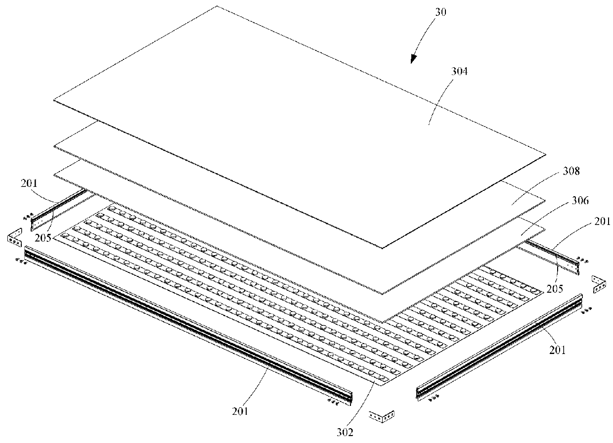
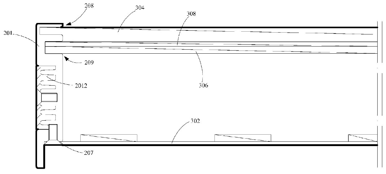
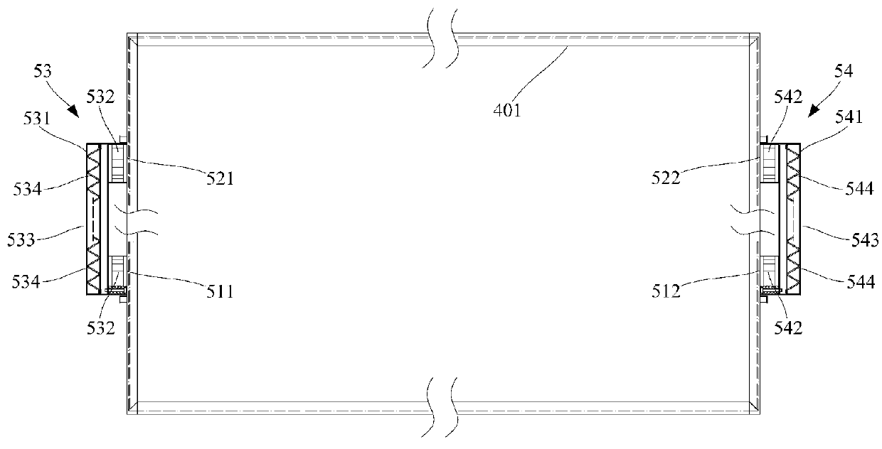
[0023]In combination of the accompanying drawings, the following description details the preferred embodiment(s) of the display module of the present invention.

[0024]A heat dissipater constructed in accordance with the preferred embodiment of the present invention adopts the theory of building an airway to generate air convection to fast dissipate heat, which is more efficient than the current art in the field of heat dissipation. The use of the first inlet and the first outlet to create an airway to dissipate the heat is a cure for the bias that air-cooling structure is not appropriate for the display module. Also, under the criteria that the air circulating inside the display module be clean, air convection inside the display module is the best resolution to solve problems caused by the accumulated heat inside the display module. In order to facilitate description and understanding, the following description is accompanied by drawings where appropriate.

[0025]With reference to FIGS...


PUM


Abstract

A display module has therein a heat dissipater, an installation frame, a LCD plate, an optical membrane, a diffusion plate and a light board respectively and sequentially received inside the installation frame, a first space defined between the LCD panel and the optical membrane. A heat dissipater has a first inlet, a first outlet both of which are defined in the installation frame and form a first airway inside the first space and a screen respectively provided to the first inlet and the first outlet. The formation of the airway facilitates air convection inside the display module, which helps dissipate heat generated from the operation of the display module.

Description

FIELD OF THE INVENTION[0001]The invention is related to the technology of heat dissipater, and more particularly, to a heat dissipater for a display module to effectively dissipate heat generated during the operation of the display module.BACKGROUND[0002]There are two types of LCD display constructions, i.e., cell and open cell during the manufacture process of a display module. In the cell structure, liquid crystal is filled in the gap between two substrates and then the two substrates are sealed to form a module, whose appearance is the same as a normal piece of glass. After the prior process is completed, connection ports are provided to a cell-based display module for external signal, i.e., open-cell. However, a backlight module is not included in the display module so made.[0003]A display module cannot illuminate by itself but through the backlight module. As result, the backlight module is crucial in the display industry. The backlight module is composed of a light source, a l...

Claims


Application Information

Patent Timeline
IPC IPC(8): G02F1/1333G02F1/1335
CPCG02F1/133385G02F1/133603G02F2001/133328G02F2001/133628H05K7/20972G02F1/133308G02F1/133504G02F2001/133331G02F2201/50G02F2201/36G02F1/133328G02F1/133628G02F1/1333H05K7/20G02F1/133331
Inventor ZHANG, QIANZHONGSUN, RUBINGU, RONGJUN
Owner KEEWIN DISPLAY CO LTD
Why Eureka
Try Eureka