Method and Apparatus for Driving Motor and Appliance

Active Publication Date: 2017-09-21
GUANGDONG WELLING ELECTRIC MACHINE MFG
View PDF1 Cites 3 Cited by
  • Summary
  • Abstract
  • Description
  • Claims
  • Application Information

AI Technical Summary

Benefits of technology

The present invention provides a method and apparatus for driving a motor and appliance. It can detect and compensate for installation errors of a Hall sensor, which can improve efficiency and reduce labor costs. The invention uses a relational model to determine the current angle, back electromotive force, and phase current of the motor, and calculates the target torque coefficient and current torque coefficient. If there is an error between the current torque coefficient and the target torque coefficient, indicating an error in the installation of the Hall sensor, the invention compensates for the error by adjusting the current angle and power supply to the motor. This can reduce the amount of power needed and the phase current required, and even if the Hall sensor is installed incorrectly, there is no need to manually re-adjust it.

Problems solved by technology

Currently, electric devices become necessities of daily life, and power consumption of a great quantity of electric devices grow with each passing day.
However, restricted by manufacturing and installation techniques, a Hall sensor inevitably has an installation error during installation.
Consequently, there is an error between a rotor position detected by the Hall sensor and an actual rotor position.
This error affects precision of controlling the motor by using the FOC technology, causing abnormal phenomena such as a decrease in efficiency of the motor, a start failure, or even a reverse start.
Such a compensation means has low efficiency and high labor costs.

Method used


Image

  • Method and Apparatus for Driving Motor and Appliance
  • Method and Apparatus for Driving Motor and Appliance
  • Method and Apparatus for Driving Motor and Appliance

Examples


Embodiment Construction

[0033]To make the objectives, technical solutions, and advantages of the present invention clearer and more comprehensible, the following further describes the present invention in detail with reference to the accompanying drawings and embodiments. It should be understood that the specific embodiments described herein are merely used to explain the present invention but are not intended to limit the present invention. To describe the technical solutions in the present invention, the following uses specific embodiments for description.

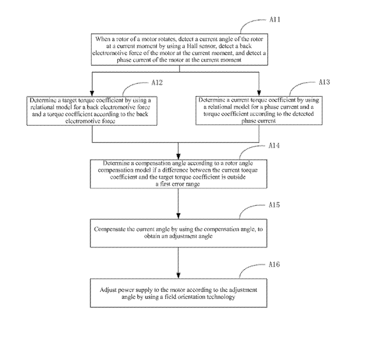
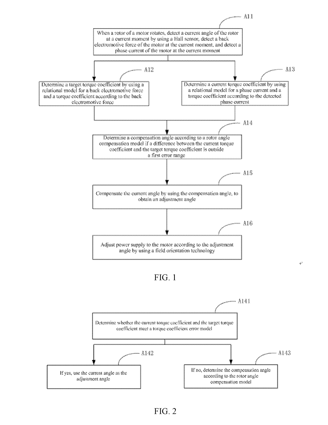
[0034]In the embodiments of the present invention, a position of a rotor in a motor is detected and determined by using a Hall sensor. Then, in a process of continuously determining the rotor by using the Hall sensor, a rotational speed of the rotor in a period of time can be determined.

[0035]It should be emphasized that, in the embodiments of the present invention, a rotor angle, the parameter used when a field oriented control (Field Oriented Control,...


PUM


Abstract

The present invention is applicable to the motor field, and provides a method and apparatus for driving motor and appliance. When a rotor of a motor rotates, a current angle of the rotor is detected at a current moment by using a Hall sensor, a back electromotive force of the motor is detected at the current moment, and a phase current of the motor is detected at the current moment; a target torque coefficient is detected by using a relational model for a back electromotive force and a torque coefficient according to the back electromotive force; a current torque coefficient is detected by using a relational model for a phase current and a torque coefficient according to the detected phase current; and a compensation angle is detected according to a rotor angle compensation model if a difference between the current torque coefficient and the target torque coefficient is outside a first error range; and the current angle is compensated by using the compensation angle, to obtain an adjustment angle; and power supply to the motor is adjusted according to the adjustment angle by using a field orientation technology. Therefore, active power required by the motor to drive a same load torque can be reduced, and a phase current required by the motor is correspondingly reduced.

Description

TECHNICAL FIELD[0001]The present invention belongs to the motor field, and in particular, relates to a method and apparatus for driving motor and appliance.BACKGROUND[0002]A permanent magnet synchronous motor has advantages such as high power density and good speed regulating performance, and is widely applied in various electric devices.[0003]Currently, electric devices become necessities of daily life, and power consumption of a great quantity of electric devices grow with each passing day. Motors take up the majority of power energy consumed by electric devices. To reduce power consumption of the motor, currently, an FOC (Field Oriented Control—field oriented control) technology is used to control power supply to the motor.[0004]When the FOC technology is used to control power supply to the motor, a position of a rotor needs to be learned in real time. In the prior art, a position sensor is usually used to detect the position of the rotor. Among numerous position sensors, a Hall ...

Claims


Application Information

Patent Timeline
IPC IPC(8): H02P6/15H02P6/08
CPCH02P6/08H02P6/15H02P6/182H02P21/20H02P6/06H02P2207/05
Inventor FU, YANCHAOGE, ZHIQIANGJIE, JIEZHAO, XIAOANGONG, LIMING
Owner GUANGDONG WELLING ELECTRIC MACHINE MFG
Why Eureka
Try Eureka