
Pneumatic tire

a technology of pneumatic tires and bead parts, applied in the field of pneumatic tires, can solve the problems of increasing heat generation, tire flexure, and large achieve the effects of reducing flexure in the bead portion, reducing flexure, and reducing flexur

Active Publication Date: 2017-09-28
SUMITOMO RUBBER IND LTD
View PDF11 Cites 14 Cited by
  • Summary
  • Abstract
  • Description
  • Claims
  • Application Information

AI Technical Summary

Benefits of technology

The present invention relates to a pneumatic tire with improved durability. The tire has a structure that prevents damage to the carcass and reduces flexure in the bead portions, which helps to maintain good ride comfort and inhibits the occurrence of flat spots. The fillers in the tire are appropriately adjusted to prevent concentration of strain and heat generation. The tire also allows for pliable flexure of the entirety of the tire and reduces heat generation in the tread. Overall, the tire has improved durability without increasing weight or cost.

Problems solved by technology

Thus, flexure occurs in the tire.
Thus, in the tire, flexure is great in bead portions thereof.
The great flexure causes strain.
The concentration of the strain may cause damage such as loosening.
Therefore, in a portion in which strain is large, not only mechanical degradation but also thermal degradation may progress.
However, in this case, a problem arises that the tire becomes heavy and, further, cost is increased.
This compression is likely to cause separation of cords included in the turned-up portions.
In the tire in which the flat spot is generated, vibration occurs during running.
The tire is poor in ride comfort.
However, this may reduce stiffness of the bead portions.
This reduces durability of the tire and ride comfort.
This may cause “tread separation” in which the surface of the tread is separated.
The tire is poor in high-speed durability.
In the tire, loosening is likely to occur between the beads and a carcass.
The tire tends to be poor in durability.

Method used


Image

  • Pneumatic tire
  • Pneumatic tire
  • Pneumatic tire

Examples


first embodiment

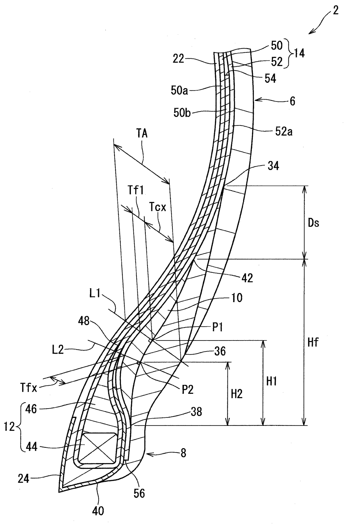
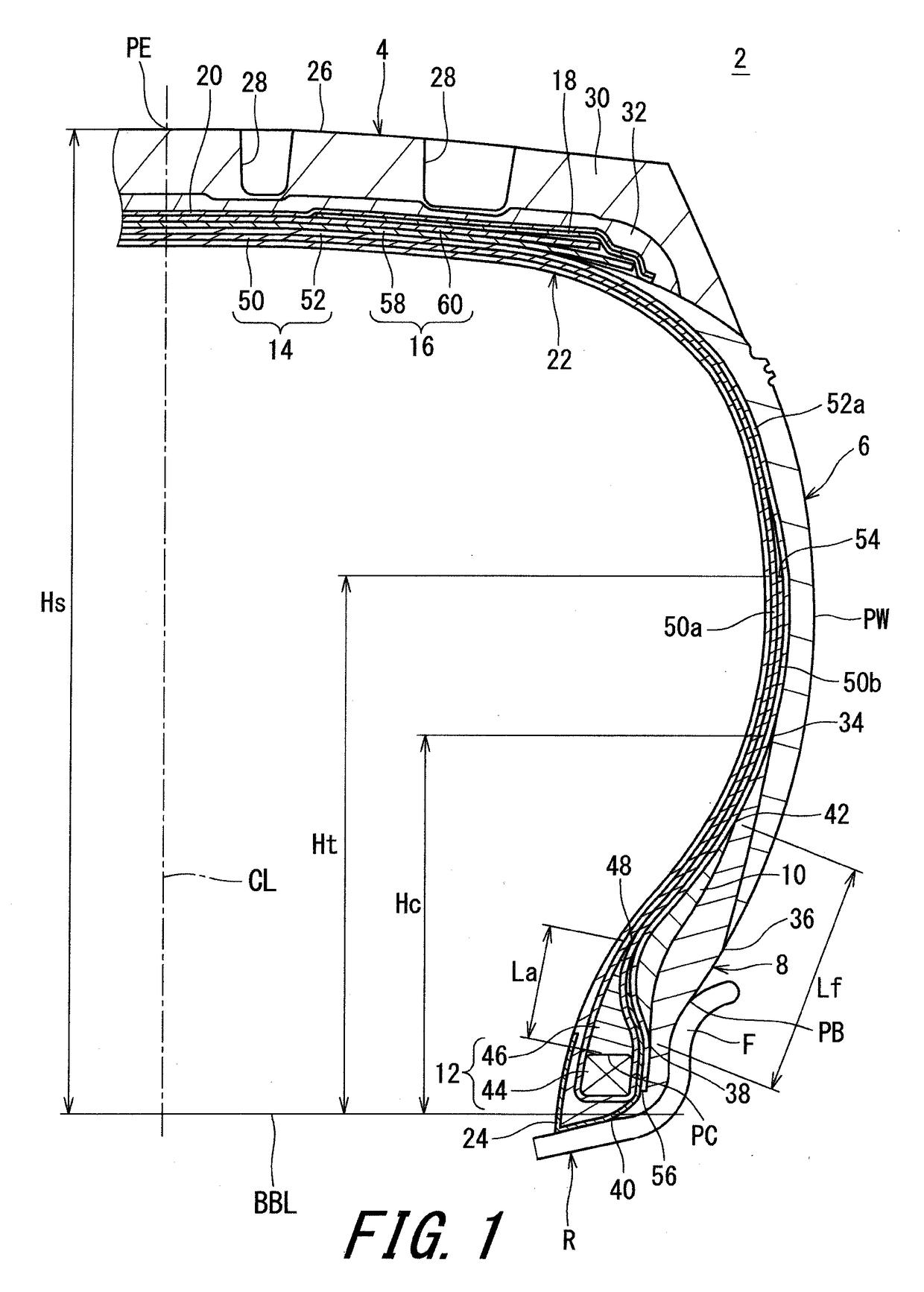
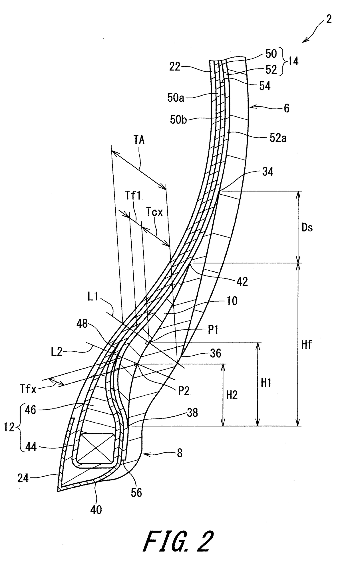
[0061]FIG. 1 shows a pneumatic tire 2. In FIG. 1, the up-down direction represents the radial direction of the tire 2, the left-right direction represents the axial direction of the tire 2, and the direction orthogonal to the surface of the drawing sheet represents the circumferential direction of the tire 2. In FIG. 1, an alternate long and short dash line CL represents the equator plane of the tire 2. The tire 2 has a shape that is symmetric with respect to the equator plane except for a tread pattern.

[0062]The tire 2 is mounted on a rim R. The rim R is a normal rim. The tire 2 is inflated with air. The internal pressure of the tire 2 is a normal internal pressure.

[0063]In the present invention, the dimensions and angles of components of the tire 2 are measured in a state where the tire 2 is mounted on a normal rim, and the tire 2 is inflated with air to a normal internal pressure, unless otherwise specified. During the measurement, no load is applied to the tire 2. In the descrip...

second embodiment

[0124]FIG. 3 shows a pneumatic tire 102. In FIG. 3, the up-down direction represents the radial direction of the tire 102, the left-right direction represents the axial direction of the tire 102, and the direction orthogonal to the surface of the drawing sheet represents the circumferential direction of the tire 102. In FIG. 3, an alternate long and short dash line CL represents the equator plane of the tire 102. The tire 102 has a shape that is symmetric with respect to the equator plane except for a tread pattern.

[0125]The tire 102 is mounted on a rim R. The rim R is a normal rim. The tire 102 is inflated with air. The internal pressure of the tire 102 is a normal internal pressure.

[0126]In FIG. 3, reference character PB represents a specific position on the outer surface of the tire 102. The position PB corresponds to an outer side edge, in the radial direction, of a contact surface on which the tire 102 and the rim R contact with each other. The position PB is a separation point...

third embodiment

[0194]FIG. 6 shows a pneumatic tire 202. In FIG. 6, the up-down direction represents the radial direction of the tire 202, the left-right direction represents the axial direction of the tire 202, and the direction orthogonal to the surface of the drawing sheet represents the circumferential direction of the tire 202. In FIG. 6, an alternate long and short dash line CL represents the equator plane of the tire 202. The tire 202 has a shape that is symmetric with respect to the equator plane except for a tread pattern.

[0195]The tire 202 is mounted on a rim R. The rim R is a normal rim. The tire 202 is inflated with air. The internal pressure of the tire 202 is a normal internal pressure.

[0196]In FIG. 6, reference character PB represents a position at an outer side edge, in the radial direction, of a contact surface obtained by the outer surface, in the axial direction, of the tire 202 and the flange surface of the rim R contacting with each other. The position PB is obtained when the t...


PUM


Abstract

In the tire 2, fillers 10 are layered over clinches 8 in portions outward of a carcass 14 in the axial direction. A carcass ply 50 is turned up around cores 44. Turned-up portions 50a are disposed between the fillers 10 and apexes 46. Each clinch 8 has a maximum thickness Tcx that is measured along a line normal to an inner surface, in the axial direction, of the clinch 8. A ratio of a thickness Tf1 of the filler 10 to a sum of the thickness Tf1 and the thickness Tcx is greater than or equal to 0.1 and not greater than 0.6. A percentage of a complex elastic modulus E*f of the filler 10 relative to a complex elastic modulus E*a of the apex 46 is greater than or equal to 70% and not greater than 125%.

Description

TECHNICAL FIELD[0001]The present invention relates to pneumatic tires. Specifically, the present invention relates to pneumatic tires for small trucks.BACKGROUND ART[0002]Tires support a vehicle body. The tires are under a load. Thus, flexure occurs in the tire. The maximum load capacity of one tire in the supporting is represented as an index. As the index, a load index is known. The load index is defined in the JATMA standard. The load index is an index that represents the maximum weight that is allowed to be applied to a tire in a specified condition.[0003]A truck runs in a state where the truck is loaded with a cargo. A truck runs in a state where the truck is loaded with a cargo that is approximately equivalent to the maximum loading capacity in some cases. In this case, the tire is under a load equivalent to the load index. Thus, in the tire, flexure is great in bead portions thereof. The great flexure causes strain. The strain tends to concentrate on a boundary between a carc...

Claims


Application Information

Patent Timeline
IPC IPC(8): B60C15/06
CPCB60C2015/0614B60C15/0603B60C15/06B60C2015/0621B60C2015/0625B60C2015/0617B60C9/2204B60C2009/2223B29D2030/486B29D2030/724B60C15/0018
Inventor MATSUMOTO, TADAOIWATA, YASUTAKAYAGYU, KENTAROYAMASHITA, FUMIKAZUUMEKITA, SHINGOKUNIYASU, YASUAKININOMIYA, HIROAKI
Owner SUMITOMO RUBBER IND LTD
Learn More