Pneumatic pressure control method for vehicle seat and pneumatic pressure control device for vehicle seat

Active Publication Date: 2017-09-28
AISIN SEIKI KK +1
View PDF2 Cites 4 Cited by
  • Summary
  • Abstract
  • Description
  • Claims
  • Application Information

AI Technical Summary

Benefits of technology

[0018]According to the present disclosure, it is possible to restrain the operation frequency of th

Problems solved by technology

However, the internal pressure of the bladder provided inside the seat changes even after the air has been filled therein, for example, due to changes of a temperature or an atmospheric pressure in the vehicle where the seat is placed, an air leak (a leak within a tolerance range), or the like factor.
However, at the time when the detection and correction of the internal pressure of the bladder is performed, operating noise, vibration, and the like

Method used


Image

  • Pneumatic pressure control method for vehicle seat and pneumatic pressure control device for vehicle seat
  • Pneumatic pressure control method for vehicle seat and pneumatic pressure control device for vehicle seat
  • Pneumatic pressure control method for vehicle seat and pneumatic pressure control device for vehicle seat

Examples


Example

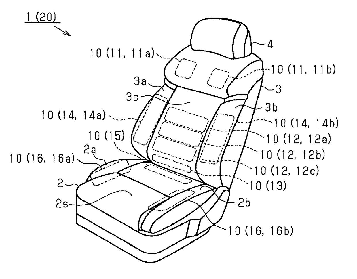
[0029]The following describes one embodiment of a seat device having an air-operated seat support function and a pneumatic pressure control thereof with reference to the drawings. As illustrated in FIG. 1, a seat 1 for a vehicle includes a seat cushion 2, and a seatback 3 provided in a rear end of the seat cushion 2. A headrest 4 is provided on an upper end of the seatback 3.

[0030]Further, in the seat 1 of the present embodiment, the seatback 3 has a shape in which both side portions 3a, 3b project forward. Further, the seat cushion 2 also has a shape in which both side portions 2a, 2b project upward. The seat 1 of the present embodiment hereby can secure a good sitting posture of an occupant and maintain the sitting posture.

[0031]Further, the seat 1 is provided with a plurality of bladders 10 (11 to 16) inside the seat cushion 2 and the seatback 3. More specifically, in the seat 1 of the present embodiment, independent bladders 11 (11a, 11b), 12 (12a to 12c), 13, 14 (14a, 14b) are ...


PUM


Abstract

A pneumatic pressure control method for a vehicle seat includes: repeatedly detecting an internal pressure of a bladder provided inside the vehicle seat at intervals; correcting the internal pressure of the bladder based on a differential pressure between a detection value and a target value; and lengthening a detection interval to detect the internal pressure depending on a time elapsing from starting of the vehicle.

Description

INCORPORATION BY REFERENCE[0001]The disclosure of Japanese Patent Application No. 2016-062306 filed on Mar. 25, 2016 including the specification, drawings and abstract is incorporated herein by reference in its entirety.BACKGROUND[0002]1. Technical Field[0003]The present disclosure relates to a pneumatic pressure control method for a vehicle seat and a pneumatic pressure control device for a vehicle seat.[0004]2. Description of Related Art[0005]There is a seat device for a vehicle, the seat device being configured such that bladders provided inside a seat are inflated and deflated so that a support shape of the seat can be changed. That is, such a seat device includes an air intake and exhaust device configured to supply (fill) air into the bladders and to exhaust the air filled in the bladders therefrom. Further, in most cases, a pressure sensor is provided in a supply passage of the air with respect to the bladders. The operation of the air intake and exhaust device is controlled ...

Claims


Application Information

Patent Timeline
IPC IPC(8): B60N2/44B60N2/02B60N2/90
CPCB60N2/0244B60N2/4415B60N2/02B60N2/90B60N2/914B60N2/52B60N2/66
Inventor SHIBATA, AKIYOSHIFUJII, YUKIODA, HIROYUKIHAYAKAWA, SHUNSUKETANAKA, SHUNSUKEHASHIMOTO, KENJIKOMAKI, SHINICHIRO
Owner AISIN SEIKI KK
Why Eureka
Try Eureka