
Knee bolster device for vehicle

a technology for bolstering devices and vehicles, which is applied in the direction of vehicle components, pedestrian/occupant safety arrangements, superstructure sub-units, etc., can solve the problems of high brittleness of the outer panel made of plastic materials, injury to the knee, and interference with inducing sufficient deformation of the shock absorption member, so as to enhance passenger safety performance and minimize injury to passengers

Active Publication Date: 2017-09-28
HYUNDAI MOTOR CO LTD +3
View PDF0 Cites 3 Cited by
  • Summary
  • Abstract
  • Description
  • Claims
  • Application Information

AI Technical Summary

Benefits of technology

The present invention provides a knee bolster device for a vehicle that can minimize injury to passengers in the event of a collision. The device includes a left support bracket and a shock absorbing foam that is supported by the right support bracket. The lower crash pad panel is reinforced with a composite material between the left and right support brackets, and front portions of the right support bracket have foam guides to guide assembly position of the shock absorbing foam and prevent abnormal deformation. This results in a more robust and effective knee bolster device that can improve passenger safety performance.

Problems solved by technology

However, although the upper part of the abdomen of the passenger's body can be protected by seat belts or air bags, it is likely that knees of passengers are struck by a cowl cross bar located below and inside a crash pad as well as a lower crash pad panel constituting a lower portion of the crash pad.
However, since brittleness of the outer panel made of plastic material is high compared to load and knee penetration amounts that are generated upon collision, sharp edges that can rather cause injury to the knee may occur when it is broken.
In addition, the inner panel made of steel material may rather interfere with inducing sufficient deformation of the shock absorbing member.

Method used


Image

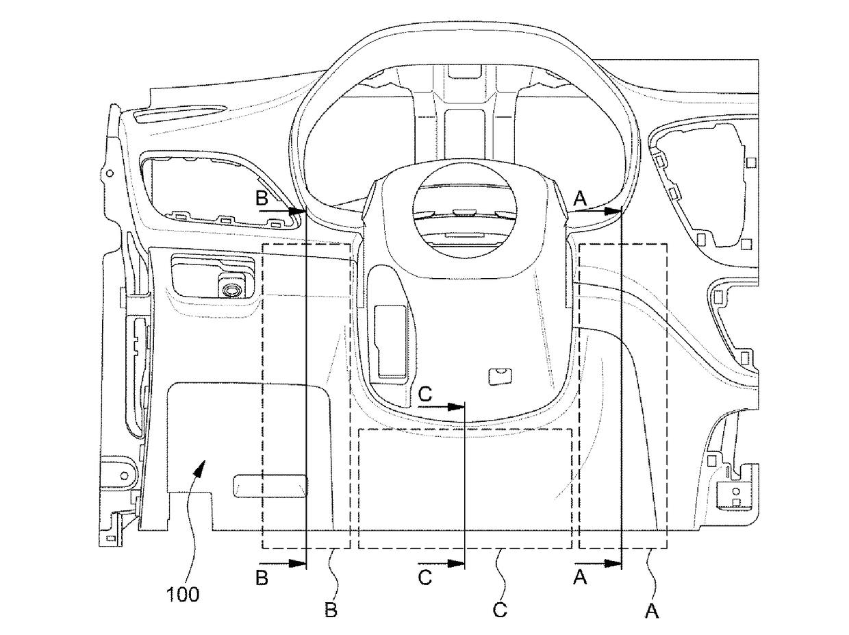
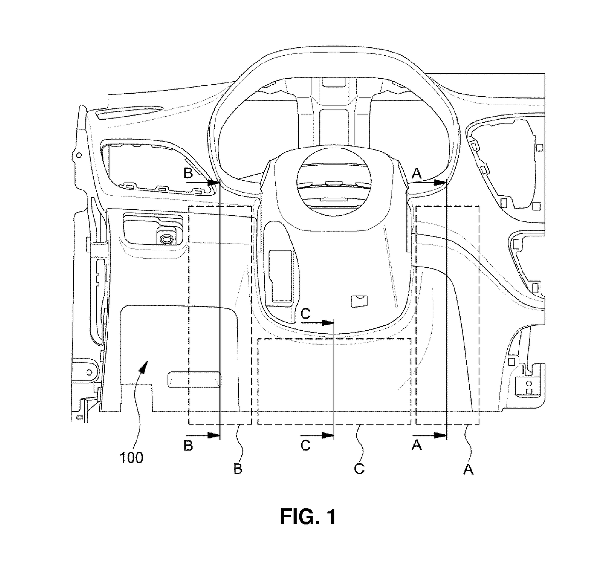
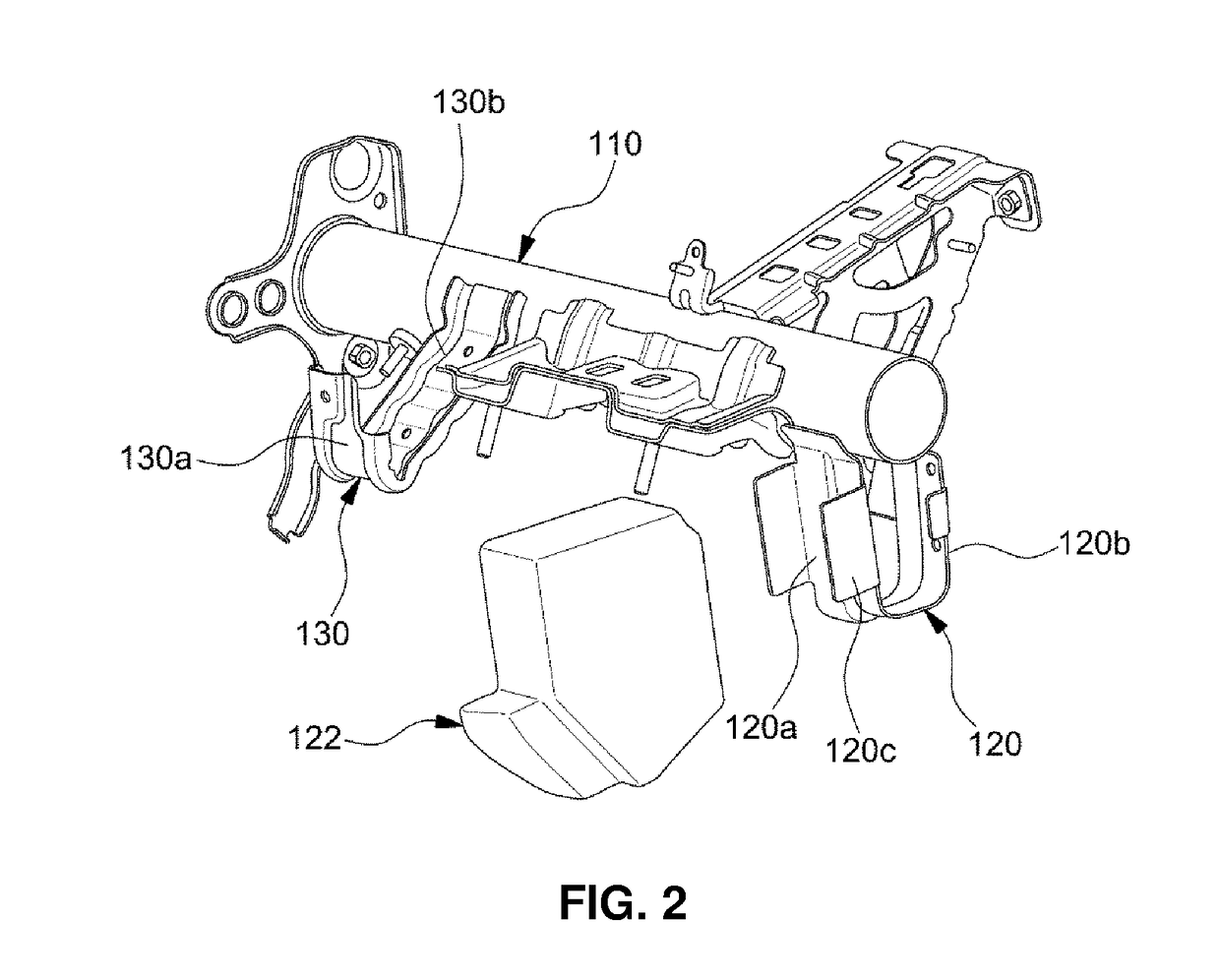
  • Knee bolster device for vehicle
  • Knee bolster device for vehicle
  • Knee bolster device for vehicle

Examples


Embodiment Construction

[0033]It is understood that the term “vehicle” or “vehicular” or other similar term as used herein is inclusive of motor vehicles in general such as passenger automobiles including sports utility vehicles (SUV), buses, trucks, various commercial vehicles, watercraft including a variety of boats and ships, aircraft, and the like, and includes hybrid vehicles, electric vehicles, plug-in hybrid electric vehicles, hydrogen-powered vehicles and other alternative fuel vehicles (e.g. fuels derived from resources other than petroleum). As referred to herein, a hybrid vehicle is a vehicle that has two or more sources of power, for example both gasoline-powered and electric-powered vehicles.

[0034]The terminology used herein is for the purpose of describing particular embodiments only and is not intended to be limiting of the invention. As used herein, the singular forms “a,”“an” and “the” are intended to include the plural forms as well, unless the context clearly indicates otherwise. It will...


PUM

PropertyMeasurementUnit
strengthaaaaaaaaaa
brittlenessaaaaaaaaaa
heightaaaaaaaaaa

Abstract

A knee bolster device for a vehicle is intended to enhance passenger safety performance by minimizing injury to passengers when a collision occurs. The knee bolster device is capable of preventing injury to passengers striking a lower crash pad panel and penetrating into an inner space of the lower crash pad panel because the lower crash pad panel is reinforced by a composite material and an impact energy absorbing structure installed in the inner space of the lower crash pad panel.

Description

CROSS-REFERENCE TO RELATED APPLICATION[0001]This application claims under 35 U.S.C. §119(a) the benefit of Korean Patent Application No. 10-2016-0035083 filed on Mar. 24, 2016, the entire contents of which are incorporated herein by reference.BACKGROUND[0002](a) Technical Field[0003]The present invention relates to a knee bolster device for a vehicle, more particularly, to a knee bolster device that is intended to enhance passenger safety performance by minimizing injury to passengers when a collision occurs.[0004](b) Description of the Related Art[0005]In general, when a vehicle is involved in a collision, passengers in the vehicle may be pushed toward a front crash pad by inertia.[0006]Therefore, vehicles are basically equipped with air bags, seat belts and the like as passenger safety devices for protecting passengers from an accident.[0007]However, although the upper part of the abdomen of the passenger's body can be protected by seat belts or air bags, it is likely that knees o...

Claims


Application Information

Patent Timeline
Patent Type & Authority Applications(United States)
IPC IPC(8): B60R21/045
CPCB60R2021/0051B60R21/045B60R21/02B60R2021/0206B60R2021/0421B29C45/14336B60R21/04B62D25/08B62D25/14B62D29/04
Inventor AN, JAE HYUNKANG, YONG HANPARK, SANG HYEONLEE, YOUNG PYO
Owner HYUNDAI MOTOR CO LTD
Learn More