Method for downhole leak detection

a leak detection and downhole technology, applied in the field of downhole leak detection, can solve the problem that the current method of finding well anomalies is not sufficiently reliabl

Inactive Publication Date: 2017-09-28
KING FAHD UNIVERSITY OF PETROLEUM AND MINERALS
View PDF5 Cites 12 Cited by
  • Summary
  • Abstract
  • Description
  • Claims
  • Application Information

AI Technical Summary

Benefits of technology

[0011]According to a first aspect, the present disclosure relates to an integrated method of determining location and type of a damage in a casing of a well, involving i) logging thickness of the casing along the depth of the well to obtain a thickness profile, ii) logging temperature along the depth of the well to obtain a temperature log, iii) logging sound frequency along the depth of the well to obtain a noise log, iv) determining the location of the damage by identifying a depth in the thickness profile where the thickness is less than a predetermined thickness threshold, v) determining the type of the damage by comparing the temperature log to a geothermal temperature log, and the sound frequency at the damage with a frequency threshold.

Problems solved by technology

Discovering the downhole leak source of pressure communication between tubing-casing and casing-casing annuli in any well, particularly at early stages, is a huge challenge for the oil industry and the key to well integrity management.
The currently employed techniques to locate well anomalies is not sufficiently reliable, therefore, a reliable methodology is needed to identify any small source of downhole leaks.

Method used


Image

  • Method for downhole leak detection
  • Method for downhole leak detection
  • Method for downhole leak detection

Examples


example 1

[0090]For downhole leak identification in oil, gas and water wells three aims were set. The first aim is to obtain different types of logs in order to find a new integrated approach. The second aim is to use the integrated method to detect downhole leaks by utilizing only rigless data based on full interpretation and evaluation of different logs in the field: temperature, noise, and thickness log. Finally, the last aim is to compare rigless approach results with conventional rig approach results for downhole leak detection.

example 2

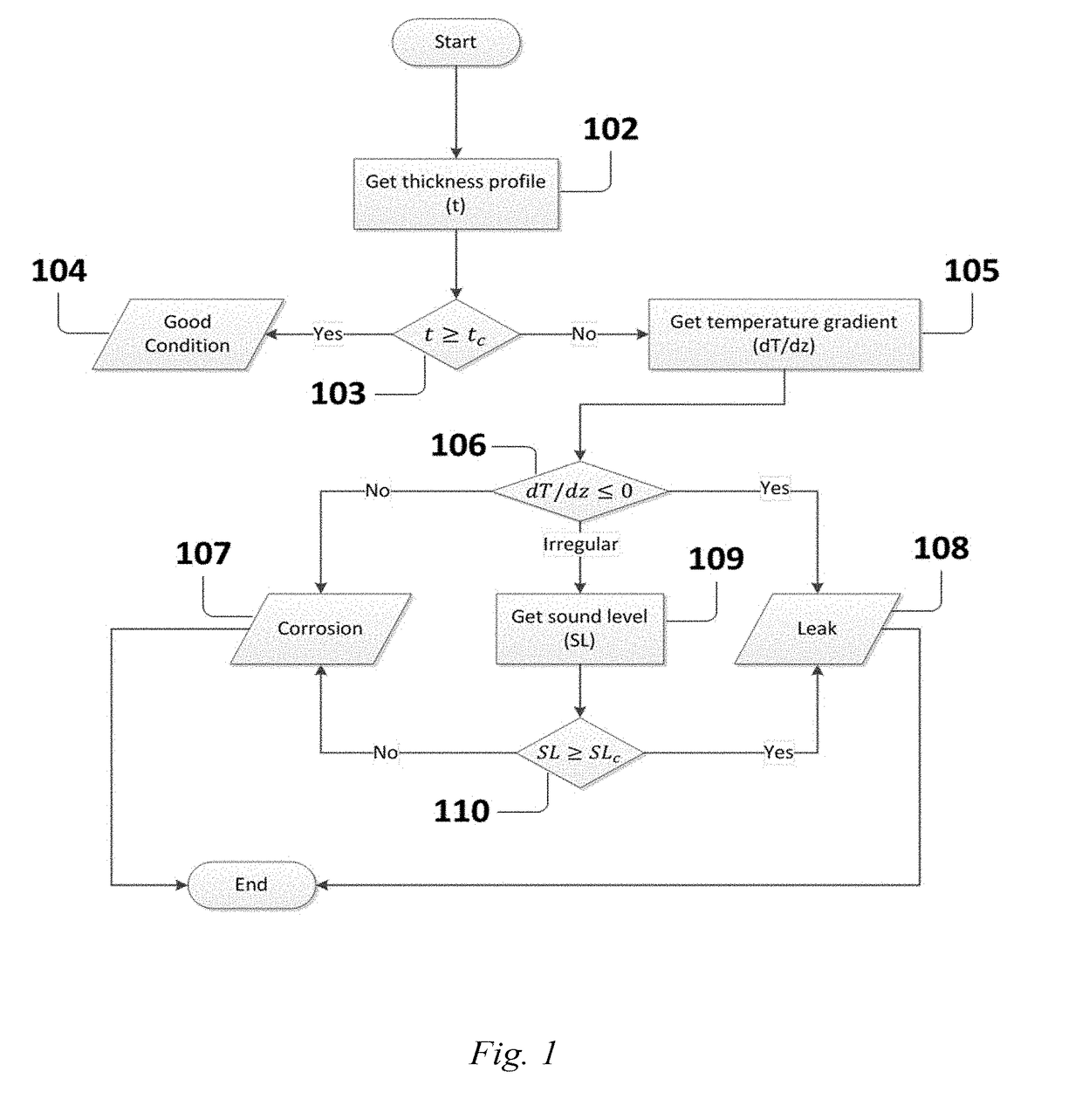
[0091]The developed integrated model is used to detect the downhole leak through analyzing only the numerical log data of corrosion, temperature and noise surveys. Based on the developed model, some instructions were implemented to allow the program decided that the completion in a specific depth is either leaked or only corroded or in a good condition. These rules were put based on these following surveys and in a specific order:

[0092]For corrosion survey, a corrosion factor was set such that, for a 4½″ tubing, 53% corrosion factor was implemented to the original tubing thickness which will indicate the presence of either corrosion or leak. If corrosion sigma (i.e. measured thickness) in a specific depth is less than 53% of the original tubing thickness, then the model highlights this location for more investigations by performing a temperature survey.

[0093]For a 7″ casing, 39% corrosion factor from the original thickness was implemented to the original casing thickness which will ...

example 3

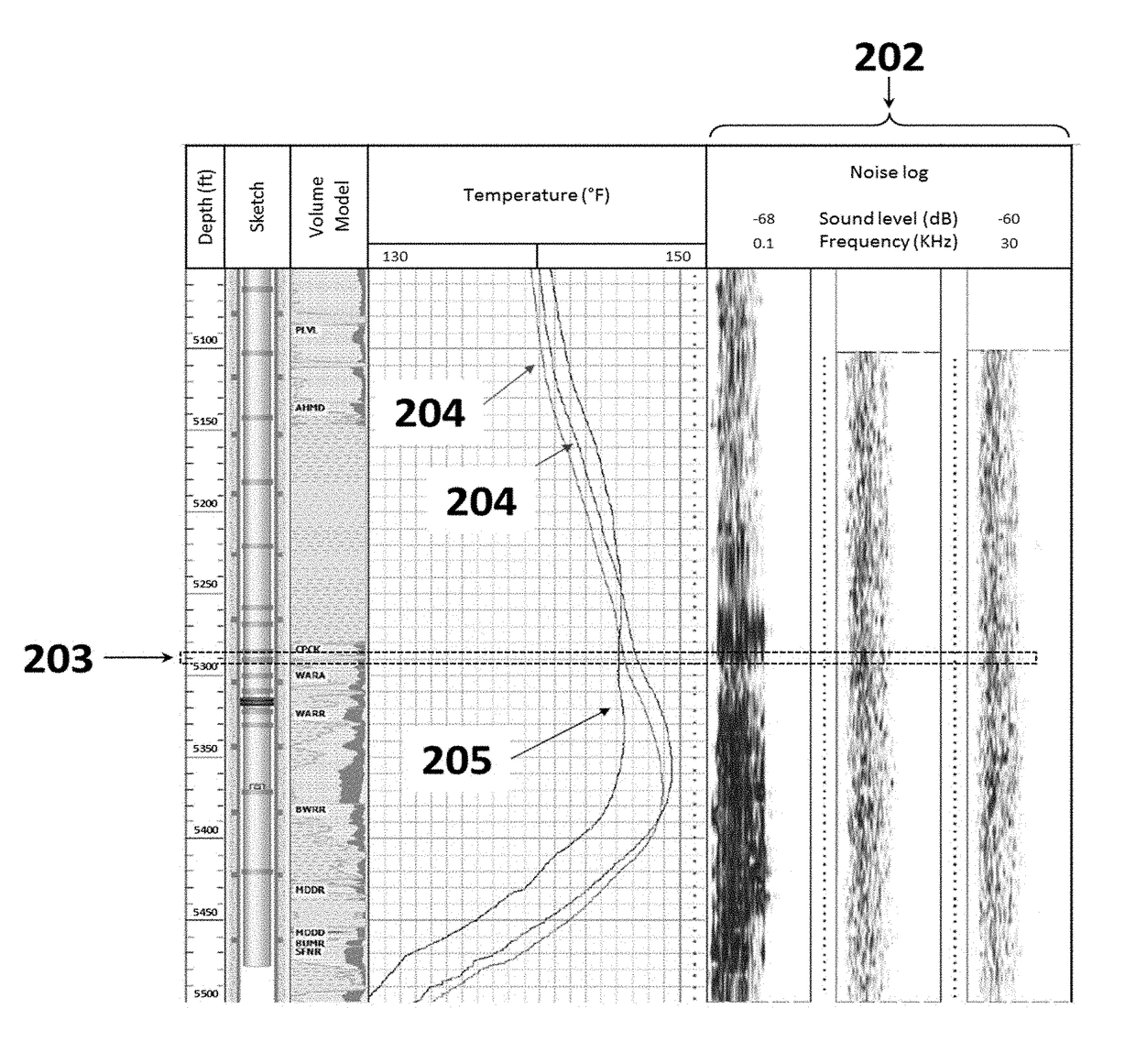
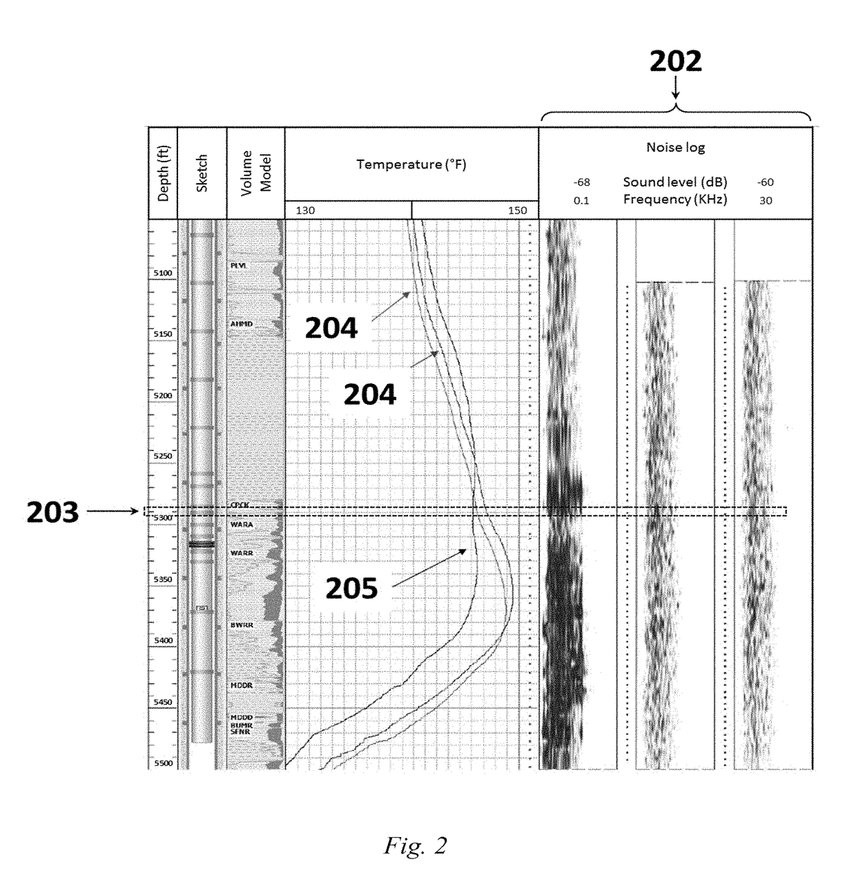
[0097]The results of the developed model verify the conventional rig approach results. However, there is still a minor difference between the developed model and the conventional rig approach results. This difference may be due to accuracy of the results implying that what is predicted by the developed model is often more accurate than a manual prediction. The maximum noticed frequency in a well was 18 KHz and the minimum was zero. So, our reference noise frequency (i.e. the frequency threshold) is 9 KHz. In this case, if the frequency in a specific depth is greater than or equal to 9 KHz, this will confirm the presence of leak only if it is supported by the presence of damage from the thickness profile and the temperature log.


PUM

PropertyMeasurementUnit
inclination angleaaaaaaaaaa

Abstract

An integrated and rigless method of determining the location and the type of damage in casing or tubing of a wellbore that involves recording a thickness profile of the casing or tubing, a temperature log, and a noise log along the depth of the wellbore, followed by locating the damage from the thickness profile, and determining the type of damage from the temperature log and the noise log.

Description

BACKGROUND OF THE INVENTION[0001]Technical Field[0002]The present invention relates to an integrated method of determining the location and the type of damage in casing or tubing of a wellbore. The method involves recording a thickness profile, a temperature log, and a noise log along the well, and further locating the damage from the thickness profile, along with determining the type of damage from the temperature log and the noise log.[0003]Description of the Related Art[0004]The “background” description provided herein is for the purpose of generally presenting the context of the disclosure. Work of the presently named inventors, to the extent it is described in this background section, as well as aspects of the description which may not otherwise qualify as prior art at the time of filing, are neither expressly or impliedly admitted as prior art against the present invention.[0005]Effective well integrity practices ensure the protection of people, facilities and the environment ...

Claims


Application Information

Patent Timeline
Patent Type & Authority Applications(United States)
IPC IPC(8): E21B47/10G01B21/08G01N17/04E21B47/06
CPCE21B47/1005E21B47/065G01N17/04G01B21/08E21B47/101E21B47/10E21B47/11E21B47/07E21B47/103E21B47/107
Inventor AL-HUSSAIN, ALI MUSAHOSSAIN, M. ENAMUL
Owner KING FAHD UNIVERSITY OF PETROLEUM AND MINERALS
Why Eureka
Try Eureka