
Hydraulic circuit for construction equipment

Inactive Publication Date: 2017-09-28
VOLVO CONSTR EQUIP
View PDF8 Cites 7 Cited by
  • Summary
  • Abstract
  • Description
  • Claims
  • Application Information

AI Technical Summary

Benefits of technology

[0055]According to the present disclosure as set forth above, it is possible to adjust the power of the hydraulic pump by adjusting the swash plate from the moment at which the weight of a piece of equipment has to be lifted by the jack-up operation and restrict the flow of hydraulic fluid by selectively supplying hydraulic fluid to the small chamber when the boom is lowered by its own weight.
[0056]In addition, the use of a load check valve

Problems solved by technology

That is, a load check function of preventing the reverse flow using the flow control valve 8 so that

Method used


Image

  • Hydraulic circuit for construction equipment
  • Hydraulic circuit for construction equipment
  • Hydraulic circuit for construction equipment

Examples


Example

DESCRIPTION OF THE REFERENCE NUMERALS IN THE DRAWINGS

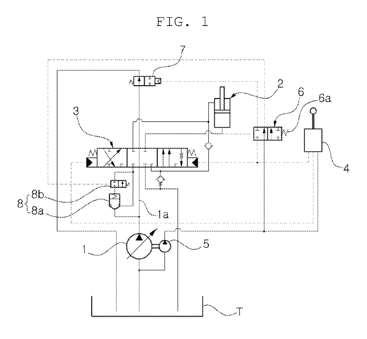
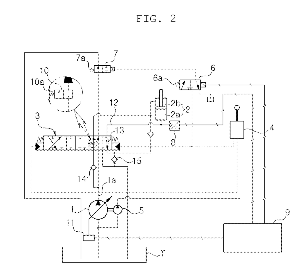
[0063]1: hydraulic pump[0064]2: hydraulic cylinder[0065]3: directional control valve[0066]4: control device (RCV)[0067]5: pilot pump[0068]6: jack-up control valve[0069]7: central bypass control valve[0070]8: pressure sensor[0071]9: controller[0072]10: flow control valve[0073]11: regulator[0074]12: regeneration passage[0075]13: orifice[0076]14: load check valve[0077]15: holding check valve

BEST MODE

[0078]Hereinafter, a hydraulic circuit system for construction equipment according to exemplary embodiments of the present disclosure will be described in detail with reference to the accompanying drawings.

[0079]FIG. 2 is a diagram of a hydraulic circuit system for construction equipment according to an exemplary embodiment, in which a large chamber supplies hydraulic fluid to a small chamber to perform hydraulic fluid regeneration when a hydraulic cylinder is driven to retract, FIG. 3 is a diagram of the hydraulic circuit system for cons...


PUM


Abstract

Disclosed is a hydraulic circuit for construction equipment for controlling to selectively supply a hydraulic oil from a hydraulic pump to a hydraulic cylinder for driving a boom. The hydraulic circuit for construction equipment, according to the present invention, comprises: a hydraulic cylinder driven by a hydraulic oil of a hydraulic pump; a direction control valve installed on the oil passage between the hydraulic pump and the hydraulic cylinder; an operating device installed on the oil passage between a pilot pump and the direction control valve; a center by-pass switching valve installed at the most downstream side of a center by-pass passage of the hydraulic pump; a pressure detection sensor that detects the pressure of a hydraulic oil at the large chamber side of the hydraulic cylinder; a jack-up switching valve installed on the oil passage between the operating device and the center by-pass switching valve; and a flow control valve installed in the spool of the direction control valve.

Description

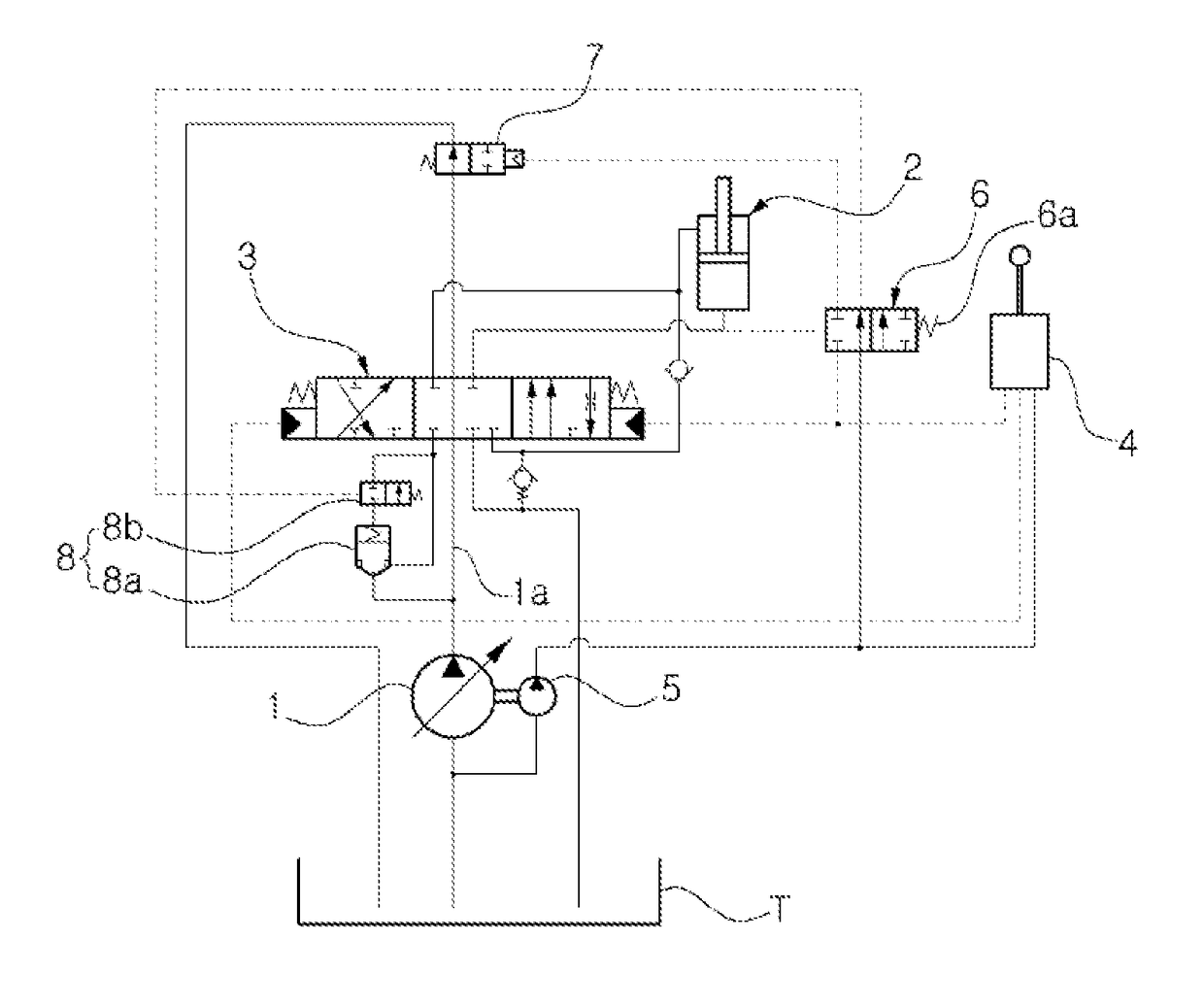
TECHNICAL FIELD[0001]The present disclosure relates to construction equipment, and more particularly, to a hydraulic circuit system for construction equipment that controls hydraulic fluid to be selectively supplied to a hydraulic cylinder driving a boom, by a hydraulic pump.BACKGROUND ART[0002]FIG. 1 is a diagram of a conventional hydraulic circuit for construction equipment.[0003]As illustrated in FIG. 1, a hydraulic cylinder 2 is connected to a variable displacement hydraulic pump (hereinafter referred to as a hydraulic pump) 1, such that the hydraulic cylinder 2 is driven by hydraulic fluid supplied by the variable displacement hydraulic pump 1. A directional control valve (MCV) 3 is disposed on a path between the hydraulic pump 1 and the hydraulic cylinder 2 to control a flow of hydraulic fluid supplied to and discharged from the hydraulic cylinder 2.[0004]A control device 4 is disposed on a path between a pilot pump 5 and the directional control valve 3 to output a control sig...

Claims


Application Information

Patent Timeline
IPC IPC(8): F15B11/10F15B21/14E02F9/22F15B13/02
CPCF15B11/10F15B2211/7053F15B21/14E02F9/2292E02F9/2285E02F9/2282E02F9/2267E02F9/2271E02F9/2217E02F9/2296E02F9/2235F15B2211/20546F15B2211/41554F15B2211/428F15B2211/6052F15B2211/6346F15B2211/6313F15B2211/6355F15B13/027E02F9/2228E02F3/435E02F9/20E02F9/22
Inventor JOUNG, HEA-GYOON
Owner VOLVO CONSTR EQUIP
Learn More